#opamps
Text
Analog Integrated Circuits
Analog Integrated Circuits (ICs) are electronic circuits that process continuous signals, such as voltage or current, as opposed to digital circuits, which operate with discrete levels representing binary values (0 and 1). Analog ICs are designed to perform functions like amplification, filtering, modulation, demodulation, and signal conditioning. These circuits are essential components in various electronic systems, including audio amplifiers, sensors, communication systems, and power management circuits.
Nomination Link :https://x-i.me/emcnom
Get Connected Here:
==================
Facebook : https://www.facebook.com/profile.php?id=61556074815651
Twitter : https://twitter.com/PencisE28647
Pinterest : https://in.pinterest.com/electronicconference/
#AnalogIntegratedCircuits#AnalogICs#OpAmps#OperationalAmplifiers#VoltageRegulators#ADCs#DACs#Comparators#AnalogFilters#AnalogSwitches#AnalogMultiplexers#AnalogDesign#SignalProcessing
0 notes
Text
i’m free................survived a whole year and only almost dropped out twice
#biomed eng#it is done#i'm exhausted#that last exam was two and a half hours of constant speedy maths#no chance to put my pen down and breathe#i had autistic extra time and didn't even finish the paper#missed a question on supernodes#smashed the opamps though! could have been much worse#i signed up for club night tonight and didn't realise i'd feel like sleeping for a year so. that's going to be tough
4 notes
·
View notes
Text
OPアンプを差し替えると動作が変わる回路
OPアンプは帰還型の回路で使うのが一般的なので、定格内の動作なら別のOPアンプに差し替えても動作は変わらないだろうと思ったら大間違いだぞという話です。
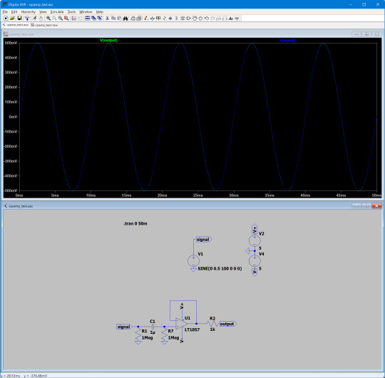
上の回路は、OPアンプを使ったバッファ回路です。入力は直流成分をコンデンサで除去するACカップリングになっていますが、出力はOPアンプの出力をそのまま(抵抗だけ入れて)出しています。後段に別の回路を組み込むような場合このような回路を使うことが多いかと思います。この回路では、OPアンプにJFETタイプのLT1057を使用しています(オーディオ系工作でよく使われるTL072と似たような特性なので、自分はLTSpiceでのシミュレーションでよく使っています)。シミュレーション結果を見ると、入力と出力はほぼ一致しています。
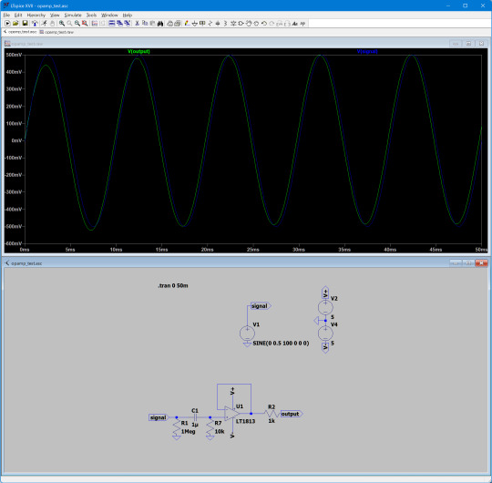
さて、回路構成は同じで、OPアンプだけを別のLT1813に変えてみたものが次の回路です。シミュレーション結果では、なんと出力に0.8Vほどのオフセット電圧が加わってしまっています!

この違いは、OPアンプの入力バイアス電流が原因で発生します。入力バイアス電流は、OPアンプの+/-それぞれの入力端子に流れ込む電流のことです(Analog Devicesによる解説資料)。データシートによると、LT1057の入力バイアス電流は標準で±7pA、最大で±75pAとされています。いっぽう、LT1813の入力バイアス電流は標準で-0.9μA、最大で±4μAとなっています(入力バイアス電流がマイナスということは、+/-それぞれの端子から電流が流れ出ることを意味しています)。
この回路では、+入力端子が1MΩの抵抗(R7)を介して接地されています。入力バイアス電流は直流なのでコンデンサ(C1)は通らず、すべてR7に流れます。入力バイアス電流が7pAの場合、これによって生じるGNDとの電位差は7μVと一般的には無視できるレベルですが、0.9μAの場合は0.9Vというかなり大きめの値になってしまいます。
このような回路構成の場合、入力バイアス電流によって発生した電圧が直接入力電圧に加算され、そのまま出力に出てきます。これは増幅率1のユニティゲイン回路ですが、たとえば非反転増幅回路の構成にした場合は入力バイアス電流によって発生した電圧も増幅されるため、より出力信号に加わるバイアス電圧は大きくなります。
入力バイアス電流の対策方法
今回のような回路では、入力端子に接続する抵抗の抵抗値を小さくすることで出力電圧に加わるバイアスを減らすことができます。たとえば、R7を100分の1の10kΩに変更すると、次のように出力と入力の差は小さくなります。
もちろん、入力バイアス電流が小さいOPアンプを選択するというのも(選択肢があるのであれば)良い解決方法でしょう。上記で紹介したAnalog Devicesの資料ではほかにもいくつかの対策方法が紹介されています。
入力バイアス電流の大きいOPアンプ
入力段にCMOSやJFETを使ったOPアンプは入力バイアス電流が小さく、バイポーラトランジスタを使ったOPアンプは入力バイアス電流が大きい傾向があります。たとえば、オーディオ用OPアンプとしてよく使われるNJM4580は入力段にバイポーラトランジスタを使っているため、入力バイアス電流が大きめで、データシートによると標準で100nA(0.1μA)、最大で500nA(0.5μA)です。TL072はJFETタイプで標準で20pA、最大で200pAなので、TL072を使った回路でOPアンプをNJM4580に差し替えると、回路によってはこの入力バイアス電流による影響を大きく受ける可能性があります。
3 notes
·
View notes
Text
The cheap IEM's I got are pretty good 90% of the time but they suffer from a severe case of IEM Oversensitivity, 105dB is just too sensitive for any amplifier chain not made with high sensitivity in mind, I had to use them for a meeting because my headset battery died and the audio solution in my work laptop sounds like a jet engine spooling up on the other end of a runway through them, hissing and crackling that you'd never normally hear on your average 90-100dB headphones.
I was looking up the stats and apparently the new model is rated at 111dB sensitivity which, you're going to cause yourself so many problems.
#this is how i end up learning about audio amplifier specifications.#we no longer live in the era of hot-swappable opamps unfortunately
7 notes
·
View notes
Text
a single voltage buffer could probably drive 2 opamps right
#hopefully#adding 1 more opamp would be annoying 2 would b alright if it was reasonable but#hm maybe ill just do a 4 opamps and use 2 duals#oh wait i think i forgor i do need another oen for a summing amp cool
0 notes
Text
Got a nice simple 555 circuit going together and it's shaking the rust from my brain. Even the basic stuff is pretty fun.
#gotta make a PNP follower next which is actually kind of new to me bc I always avoided PNPs#then I can hook that to the LPF and play with signal shaping#not sure yet if I'll just use a cookbook opamp one or a transistor one
0 notes
Text
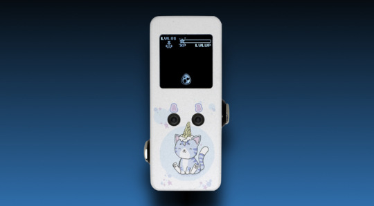
Ground Control UwU Virtual Pet Buffer - With OLED virtual pet
Ground Control introduces the groundbreaking UwU Virtual Pet Buffer, ingeniously combining the charm of ’90s Tamagotchi with the functionality of a high-quality buffer pedal. Preorders are now open for this unique pedal, set to be delivered in March 2024.
Embrace the Retro Vibe: Tamagotchi Meets Modern Music Tech
Reminiscent of a classic 1990s toy, the UwU Virtual Pet Buffer isn’t just for show.…
View On WordPress
#buffer#Ground Control#Ground Control UwU Virtual Pet Buffer#op amp#opamp#opamp-based#UwU Virtual Pet Buffer#video#virtual pet#YouTube
0 notes
Photo
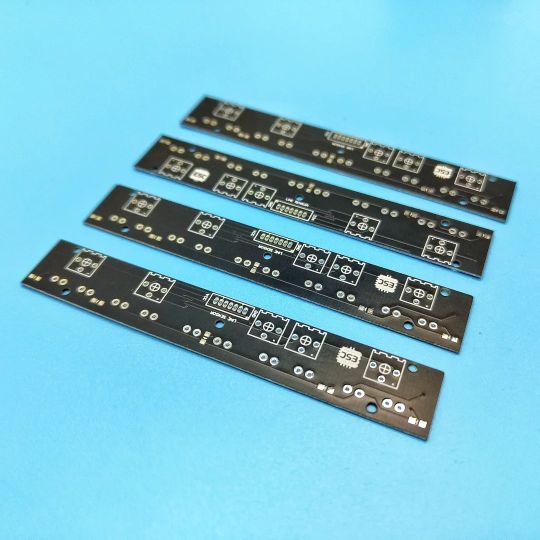
I MADE A custom line sensor array for my line follower robot. It has 5 IR CHANNELS individual sensing adjustment LED indication @jlcpcb #linefollowerrobot #linefollower #ir #irsensor #irmodule #qtr #pololu #robotics #pcb #electronics #makers #lm358 #opamp #led https://www.instagram.com/p/Cpm_HwsrfT3/?igshid=NGJjMDIxMWI=
#linefollowerrobot#linefollower#ir#irsensor#irmodule#qtr#pololu#robotics#pcb#electronics#makers#lm358#opamp#led
1 note
·
View note
Text
Low pass opamp filter designer

#LOW PASS OPAMP FILTER DESIGNER HOW TO#
#LOW PASS OPAMP FILTER DESIGNER INSTALL#
#LOW PASS OPAMP FILTER DESIGNER PC#
Since we’re designing a broadcast-reject filter for 160 meter reception, we need a high-pass response. (Filter basics were covered in the previous column.) This is the filter’s topology describing the general arrangement of the filter components. Now it’s time to tell ELSIE what kind of circuit you want.
#LOW PASS OPAMP FILTER DESIGNER INSTALL#
Using ELSIEīegin by downloading the current version of ELSIE (2.82 as of mid-June 2018) from Tonne Software ( Follow the install wizard’s instructions, then run ELSIE.
#LOW PASS OPAMP FILTER DESIGNER HOW TO#
By stepping through a sample design, you’ll get a feel for how to turn specifications like we discussed in the last column into a real filter design. In this column, I’ll illustrate the time-tested and free student version of ELSIE: Design software for passive filters made from inductors (L) and capacitors (C) thus, the name, L-C. You have to provide all the component values before determining how the circuit will work. Remember that simulator programs such as LTSpice ( en./wiki/LTspice) require that you come up with a design first. An advantage of proprietary design tools, generally, is that they take into account more component characteristics and can help avoid trouble in high-performance designs. Proprietary websites may only use components that are produced by that company, but if your filter doesn’t have extreme requirements, you can often switch to equivalent parts by any company. The supported filter designs can be active (op-amp based), passive (RC, RL, RLC), or both.
#LOW PASS OPAMP FILTER DESIGNER PC#
Some are stand-alone software you install on your PC and others run on a website (usually a company’s website). There are quite a few software packages and services to choose from. Luckily for hams and other experimenters, there are plenty of free or low-cost programs to try (see the sidebar). There are several filter design software packages ranging from simple calculators to sophisticated CAD programs. Sounds like a job for some filter design software, doesn’t it? Practically, you’ll need to build the filter with standard-value components as well, and that will affect filter performance too. There are tables and equations, but they are tedious to work with. So far, so good, but a filter that doesn’t attenuate signals very much above 1.8 MHz while attenuating them significantly in the adjacent broadcast band is not a simple thing to design. The usual solution is to install a high-pass broadcast-reject filter at the receiver input, attenuating the unwanted AM signals below 1.6 MHz while passing the desired 160 meter signals with little attenuation. Antennas for those frequencies pick up a lot of AM band RF, overloading the input circuits and creating distortion or false signals inside the receiver. Hams often experience fundamental overload on the 160 meter band (1.8–2.0 MHz) which is adjacent to the AM broadcast (BC) band (550 kHz–1.7 MHz). The AM signal is completely legal but just too strong, disrupting the function of the receiver or overriding the desired programming. The receiver might be a wireless telephone, a scanner, or even a TV or radio receiver. It occurs when a receiving device is functioning entirely properly but unable to reject a strong signal. If you’ve ever lived close to an AM broadcast station, you probably experienced the phenomenon known as fundamental overload. » Skip to the Extras Once you start, it’s hard to stop!
0 notes
Text
Low pass opamp filter designer

You can modify active filter circuits to sum multiple inputs together by following the simple steps described in this article. The purpose of the LPF is to allow only low-frequency signals and block high-frequency signals.Modifying a 2V/V SK high-pass filter to a unity-gain two-input summing filter with AC results Thus, this is all about an overview of the low pass filter circuit using an op-amp, a basic LPF circuit, first-order active LPF, second-order active LPF, low pass filter calculator, and applications. Please refer to this link to know more about Band Pass Filter MCQs, FIR Filter MCQs and High Pass Filter MCQs Used in wave analyzers, audio amplifiers, and equalizers.Used in electronic applications like loudspeakers, subwoofers, etc.Used to remove the noise of high-frequency signals.The low pass filter applications include the following. The frequency response characteristics are drawn between gain (dB) and frequency (Hz).Īt the low frequencies, the gain of the LPF is higher than the passband gain of the filterĪt high frequencies, the gain of the LPF is less than its passband gain and it falls to -20dBĪs the frequency increases, the output voltage falls 70.71% below the input voltage. The equation of capacitive reactance in ohms of the LPF circuit is given as The cut-off frequency of the LPF circuit is, To calculate the gain and phase shift of the LPF,Ĭonsider ω = 1/RC and ω = ωc for the above equationĬonsider f = operating frequency and fc = cut-off frequency If ω = infinity then the magnitude of the transfer function = 0 If ω = 1/ CR then the magnitude of the transfer function = 0.707 If ω = 0 then the magnitude of the transfer function = 0 The magnitude of the transfer function is calculated with the help of ‘ω’ i.e, angular frequency We can calculate the magnitude of the transfer function from the above equation. Please refer to this link for Low Pass Filter MCQsįrom the LPF circuit diagram (RC circuit), we can observe that ‘Vi’ is the applied input voltageīy the transfer function of the circuit, we get LPF CalculatorĪ low pass filter calculator is the calculation of cut-off frequency, voltage gain, and the phase shift of the LPF circuit. The circuit diagram of second-order active LPF is shown below. So, the gain of the second-order active LPF is -6dB at the cut-off frequency i.e, gain increased twice. We know that the gain of the first order active LPF is -3dB at the cut-off frequency. The name LPF itself indicates low range frequency. What is a Low Pass Filter?ĭefinition: The filter circuit which allows only low pass frequency components and blocks all other higher frequency components is called a low pass filter. This article describes the low pass filter using op-amp (active element), which is also called an active LPF. These types of filter circuits come under the passive filter category because the passive elements resistor, capacitor, and inductors are used in the circuit. They are low pass filters, high pass filters, bandpass filters, and bandstop filters. Filter circuits are divided into four types based on the range of frequencies that the circuit would allow while blocking all other frequencies. For example, in radio or tv, a tuning filter circuit rejects unwanted frequencies by allowing only the desired channel. In electronic devices, the filters are the circuits that allow desires frequency components and blocks all other frequency components of a signal.
0 notes
Text

AMZFX - FET Tubes Fuzz
"Another ancient pedal from the boxes in my garage. This one has the same type LMB folded aluminum enclosure. It also uses the cmos switching system with a soft-touch footswitch that has been broken over the years and the top pad is missing.
I am not sure what the circuit is in this pedal but I opened it up and took a quick peek inside. I could not get much of a view without removing the pots and jacks, but it looks to be using an opamp and a couple of jfet transistors.
The clear finish is dirty just like the previous pedal, and not easily removed or cleaned. The labels appear to be dot-matrix printed on adhesive backed label stock, cut out and then stuck in place. The clearcoat was applied last over the labels and paint.
At some point I stole the knobs to be used on some other project."
cred: muzique.com/news/fet-tubes, instagram.com/amzfx
33 notes
·
View notes
Note
Hey I just need to say absolutely adore your work here it has helped people such as me soo much on pretty much everything you need to know about their gear and I wanted to ask if I can’t spend that much money on an Marshall shredmaster what pedal can you recommend that is cheap that delivers that Marshall in a box sound as I bought an fender 85 today and I’m just stuck on what pedal to pick that is student budget friendly and can you possibly help with what amp settings jonny used in glastonbury 2003? Help would be much appreciated!
Just get a used ProCo Rat (standard version) and focus in your playing. Jonny didn't use one, but there's a reason so many people think he did: with the filter knob set right, the Rat has a similarly focused tone to the Shredmaster in the mids and highs.
The Shredmaster and Rat both use opamp hard-clipping followed by diode soft-clipping, so it's not a surprise they're similar (however, the Shredmaster has two stages of opamp clipping). The Rat lacks the post-clipping bass boost of the Shredmaster, but you can compensate for that with amp settings. Obviously, the Rat is less versatile than the Shredmaster, since it can't create scooped tones. But it does a good job of Jonny's favorite Shredmaster setting: contour knob at minimum for full mids and no scoop.
A bonus of getting a cheap, used Rat is you can quite easily modify it with a "clipping" switch, which gives access to Turbo Rat tones (the Turbo was Thom's favorite drive in the 90s, and that's probably the reason people used to think Jonny used a regular Rat). You can also get a Turbo Rat and add a switch for regular Rat tones, but the Turbo is usually pricier. Or, if you're particularly interested in soldering, you can build a mini Rat clone for about the price of a used regular Rat.
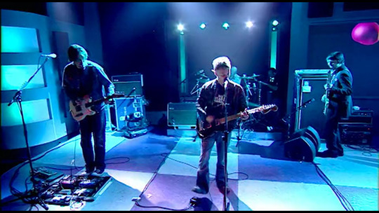
A shot of Thom about to stomp on his ProCo Turbo Rat during 2+2=5 on the Jonathan Ross show on November 7, 2003 (youtube).
Another Radiohead-related option is a Boss OD3, one of Jonny's favorite overdrives since ~2006. The OD3 has a distinctive tone of its own, but with the tone set right it has a bit of Marshall flavor too. And, like the Shredmaster, it has a post-clipping bass boost for a fuller sound. I also think it's a nice starter pedal, since it's more dynamic and "amp-like" than the Shredmaster and Rat (that's due to the OD3's discrete-opamp soft-clipping circuitry). It's quite usable from low to mid to high gain, so it could easily be your only drive pedal.
For settings, check the Fender Eighty-Five entry on Jonny's amplifiers page. But remember: even replicating his settings exactly will still sound different from studio recordings, because you're missing the signal chain after the amp's speaker (mic, EQ, compression, gates, etc). So (as always) it's better to use your ears and tweak the settings to find those sounds. We discuss this in more detail in this post.
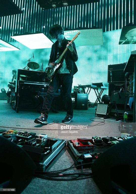
A photo of Jonny performing with Radiohead in Kansas City in 2012 (Jason Squires). You can see his Shredmaster and his OD3 on the board on the left.
8 notes
·
View notes
Photo
Tennis for Two (1958), the first video game ever, displayed on an oscilloscope. There is no source code, since it was implemented entirely in hardware. There are relays that control the direction of the ball, comparators that detect when it hits the ground or the net, opamps that implement the differential equation for the bounce of the ball, resistors that simulate drag, and so on.
22 notes
·
View notes
Text
youtube
On this fine Sunday morning, we've got another sweeeeet pedal from Twilight Pulse Audioworks - the Proxima Overdrive Fuzz!! This one is is fully hand built with high-quality through hole components, clips with a pair of NOS RFT Silicon Diodes, and operates using an obsolete NOS Harris/Intersil CA3260E BiMos Opamp…check out our demo video below, cheers!!
#pedaloftheday#twilightpulse#twilightpulseaudioworks#Proxima#ProximaCentauri#overdrive#overdrivepedal#fuzz#fuzzpedal#effectspedals#guitar#pedals#effects#pedalsandeffects#guitareffects#pedalboard#guitarist#guitars#Youtube
5 notes
·
View notes
Text
texas instruments stop obsoleting parts i want challenge
1 note
·
View note
Text
I went into music tech to make music on my puter, not fuck around with whatever the hell an opamp is
2 notes
·
View notes
Last Seen Blogs

esper-octopus
FAIL! maximizer maximizer!

sourikata
but i don't miss the misery


tattoopop
Artwork and Tattoos by Jopie Lee

hipstergenius
ill-literature