#Low pass opamp filter designer
Text
Low pass opamp filter designer

#LOW PASS OPAMP FILTER DESIGNER HOW TO#
#LOW PASS OPAMP FILTER DESIGNER INSTALL#
#LOW PASS OPAMP FILTER DESIGNER PC#
Since we’re designing a broadcast-reject filter for 160 meter reception, we need a high-pass response. (Filter basics were covered in the previous column.) This is the filter’s topology describing the general arrangement of the filter components. Now it’s time to tell ELSIE what kind of circuit you want.
#LOW PASS OPAMP FILTER DESIGNER INSTALL#
Using ELSIEīegin by downloading the current version of ELSIE (2.82 as of mid-June 2018) from Tonne Software ( Follow the install wizard’s instructions, then run ELSIE.
#LOW PASS OPAMP FILTER DESIGNER HOW TO#
By stepping through a sample design, you’ll get a feel for how to turn specifications like we discussed in the last column into a real filter design. In this column, I’ll illustrate the time-tested and free student version of ELSIE: Design software for passive filters made from inductors (L) and capacitors (C) thus, the name, L-C. You have to provide all the component values before determining how the circuit will work. Remember that simulator programs such as LTSpice ( en./wiki/LTspice) require that you come up with a design first. An advantage of proprietary design tools, generally, is that they take into account more component characteristics and can help avoid trouble in high-performance designs. Proprietary websites may only use components that are produced by that company, but if your filter doesn’t have extreme requirements, you can often switch to equivalent parts by any company. The supported filter designs can be active (op-amp based), passive (RC, RL, RLC), or both.
#LOW PASS OPAMP FILTER DESIGNER PC#
Some are stand-alone software you install on your PC and others run on a website (usually a company’s website). There are quite a few software packages and services to choose from. Luckily for hams and other experimenters, there are plenty of free or low-cost programs to try (see the sidebar). There are several filter design software packages ranging from simple calculators to sophisticated CAD programs. Sounds like a job for some filter design software, doesn’t it? Practically, you’ll need to build the filter with standard-value components as well, and that will affect filter performance too. There are tables and equations, but they are tedious to work with. So far, so good, but a filter that doesn’t attenuate signals very much above 1.8 MHz while attenuating them significantly in the adjacent broadcast band is not a simple thing to design. The usual solution is to install a high-pass broadcast-reject filter at the receiver input, attenuating the unwanted AM signals below 1.6 MHz while passing the desired 160 meter signals with little attenuation. Antennas for those frequencies pick up a lot of AM band RF, overloading the input circuits and creating distortion or false signals inside the receiver. Hams often experience fundamental overload on the 160 meter band (1.8–2.0 MHz) which is adjacent to the AM broadcast (BC) band (550 kHz–1.7 MHz). The AM signal is completely legal but just too strong, disrupting the function of the receiver or overriding the desired programming. The receiver might be a wireless telephone, a scanner, or even a TV or radio receiver. It occurs when a receiving device is functioning entirely properly but unable to reject a strong signal. If you’ve ever lived close to an AM broadcast station, you probably experienced the phenomenon known as fundamental overload. » Skip to the Extras Once you start, it’s hard to stop!
0 notes
Text
Low pass opamp filter designer

You can modify active filter circuits to sum multiple inputs together by following the simple steps described in this article. The purpose of the LPF is to allow only low-frequency signals and block high-frequency signals.Modifying a 2V/V SK high-pass filter to a unity-gain two-input summing filter with AC results Thus, this is all about an overview of the low pass filter circuit using an op-amp, a basic LPF circuit, first-order active LPF, second-order active LPF, low pass filter calculator, and applications. Please refer to this link to know more about Band Pass Filter MCQs, FIR Filter MCQs and High Pass Filter MCQs Used in wave analyzers, audio amplifiers, and equalizers.Used in electronic applications like loudspeakers, subwoofers, etc.Used to remove the noise of high-frequency signals.The low pass filter applications include the following. The frequency response characteristics are drawn between gain (dB) and frequency (Hz).Īt the low frequencies, the gain of the LPF is higher than the passband gain of the filterĪt high frequencies, the gain of the LPF is less than its passband gain and it falls to -20dBĪs the frequency increases, the output voltage falls 70.71% below the input voltage. The equation of capacitive reactance in ohms of the LPF circuit is given as The cut-off frequency of the LPF circuit is, To calculate the gain and phase shift of the LPF,Ĭonsider ω = 1/RC and ω = ωc for the above equationĬonsider f = operating frequency and fc = cut-off frequency If ω = infinity then the magnitude of the transfer function = 0 If ω = 1/ CR then the magnitude of the transfer function = 0.707 If ω = 0 then the magnitude of the transfer function = 0 The magnitude of the transfer function is calculated with the help of ‘ω’ i.e, angular frequency We can calculate the magnitude of the transfer function from the above equation. Please refer to this link for Low Pass Filter MCQsįrom the LPF circuit diagram (RC circuit), we can observe that ‘Vi’ is the applied input voltageīy the transfer function of the circuit, we get LPF CalculatorĪ low pass filter calculator is the calculation of cut-off frequency, voltage gain, and the phase shift of the LPF circuit. The circuit diagram of second-order active LPF is shown below. So, the gain of the second-order active LPF is -6dB at the cut-off frequency i.e, gain increased twice. We know that the gain of the first order active LPF is -3dB at the cut-off frequency. The name LPF itself indicates low range frequency. What is a Low Pass Filter?ĭefinition: The filter circuit which allows only low pass frequency components and blocks all other higher frequency components is called a low pass filter. This article describes the low pass filter using op-amp (active element), which is also called an active LPF. These types of filter circuits come under the passive filter category because the passive elements resistor, capacitor, and inductors are used in the circuit. They are low pass filters, high pass filters, bandpass filters, and bandstop filters. Filter circuits are divided into four types based on the range of frequencies that the circuit would allow while blocking all other frequencies. For example, in radio or tv, a tuning filter circuit rejects unwanted frequencies by allowing only the desired channel. In electronic devices, the filters are the circuits that allow desires frequency components and blocks all other frequency components of a signal.
0 notes
Text
I fucking love vactrols. At this admittedly still very early stage of my days as an audio electronics hobbyist, it seems to me like pretty much everything is just clever rearrangements of four key components: resistors, capacitors, opamps, and diodes. Pick a layout and set of values according to application, and away you go.
The ICs you see in most "true" analogue circuits? Bundles of opamps.
The knobs on the front? Potentiometers, i.e. resistors whose resistance varies with knob position.
LEDs? Diodes that emit light. Clue's right there in the name.
But of course modular wouldn't be modular without the magic of voltage control. Signals controlling other signals. Invisible hands to turn the knobs for you.
And this presents a problem in my simplistic view of the field: with the exception of potentiometers, all these components do very specific jobs, over ranges set in stone based on their physical properties, to be listed ad nauseum on the inscrutable pages of online component stores. And the potentiometers? They need real hands to turn them. Hands neither invisible nor automatic. Hands of which I only possess two. What do you want me to do, use motors or something? What do you think this is, mechanical engineering?

No! We demand ethereal hands. Electronic hands. We demand control over more than two parameters at once, without resorting to such crass concepts as physical motion, and without unleashing our biblically accurate forms upon the delicate psyches of our listeners.
Well, reader, in a carefully constructed act of lying by omission, I have hitherto neglected to mention our saving grace: the LDR, or light-dependent resistor. A magical resistor whose precise resistance varies depending on its degree of illumination.
So. We have LEDs, that emit an amount of light proportional to the current running through them. And we have LDRs, whose resistance varies depending on the amount of light falling on them. Surely it can't be that simple? Surely the answer to our voltage-control conundrum can't lie in simply mashing these two together and calling it a day?
Presenting, dear gentlefolk, the mighty vactrol.
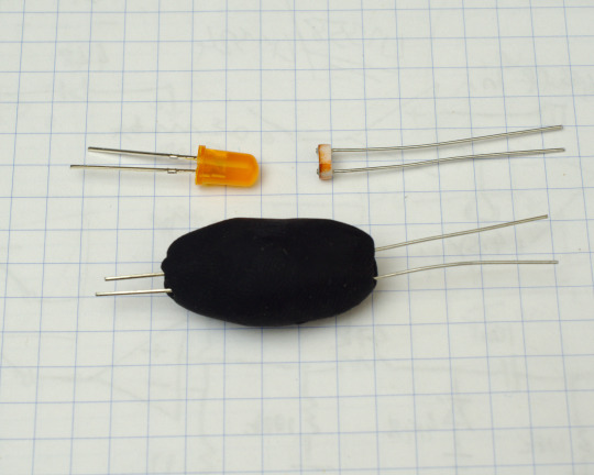
Source
(The actual filter being built there is not very interesting, it's just a passive, non-resonant LPF, but it's voltage controlled by a homemade vactrol.)
Yup. It really is that simple. So next time you are about to embark upon the study of an unfamiliar field, unsure of whether your feeble smooth brain will be capable of grasping the arcane magicks within, remember the humble vactrol.

Of course, there are also transistors. But those simply aren't as entertaining.
Disclaimer: I haven't built any of my own yet, and in fact am still at the stage of my electronics hobby where I have a ton of plans and barely any real-world practical experience beyond soldering other people's designs from kits. But I'm building up to the point where I have just enough basic knowledge and a suitable parts stash to start building some basic things from scratch, and these will probably be in my future if I take well to it.
#modular synth#diy#electronics#it's a cool name too#vactrol#smooth brain#synth#eurorack#biblically accurate electronic musician
2 notes
·
View notes
Text
Audioengine D1 Drivers For Mac

Audioengine D1 Drivers For Mac Os
Audioengine D1 Windows 10 Driver
Audioengine D1 Firmware
Audioengine D1 Premium 24-bit DAC (digital-to-analog converter) allows you to bypass your computer's soundcard or headphone output and send audio through USB or optical. D1 is the perfect digital interface between your computer and music system and will improve the sound of ALL your music.
VERSATILE
Be warned: Audioengine’s just-announced D1 ($169) is for serious audiophiles only—guys who would consider putting jet fuel in a Ferrari for just a hint of extra speed. But we know you’re out there, so here it is: D1 is a digital-to-analog converter box for your Mac that promises to “improve the sound of ALL your music” by routing it.
(The company also makes the older, $169 D1 Premium 24-bit DAC, which is larger but offers an optical-digital input, RCA outputs, a hardware volume knob, and 176.4 and 192 kHz capability.
The D1 accepts inputs from both USB and optical and has outputs for any audio system or headphones. The D1 DAC is the perfect way to get great-sounding music not only from your computer but also from your TV, Apple TV, DVD/BluRay player or CD player. And since it's powered by USB, D1 is also a high-quality portable computer headphone amplifier.
D1 DAC Highlights: Desktop or portable digital-to-analog convertor Mac or PC plug-and-play no drivers to install High-performance headphone amp included USB and optical inputs USB-powered no separate power supply needed Stream bit-perfect HD audio with low jitter Based on high-performance AK4396 DAC D1 USB The D1 utilizes the TI1020B USB controller widely recognized as a standard for higher-end USB. Jul 10, 2020 Nov 24, at 7: I have a HP Pavillion Windows 10 desktop and am using a Audioengine D1 usb dac to run my powered speakers and headphones via usb cable. The D1 is a nice looking unit, so I will still keep it on the list for now. This site uses cookies to help personalise content, tailor your experience and to keep you logged in if you register.
DESIGNED FOR THE COMPUTER AUDIOPHILE
D1 will process digital audio at any bit depth up to 24 bits and any sample rate to 192KHz. With it's high signal-to-noise ratio and low distortion the D1 delivers sound quality generally heard only in more expensive DACs. The high-performance headphone output was designed for a wide range of headphones and will satisfy even the most demanding headphone enthusiasts.
EASY SETUP
Audioengine D1 Drivers For Mac Os
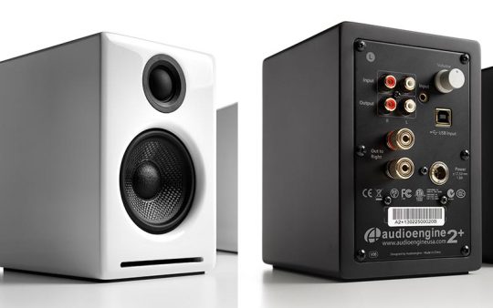
Setup is easy and no special software is needed, making D1 a true plug-and-play solution. The D1 outputs connect to any audio system or powered speakers, such as the Audioengine A5+ or A2. Power for the D1 is provided via the USB bus so there is no external power supply to connect.
D1 USB
The D1 utilizes the TI1020B USB controller, widely recognized as a standard for higher-end USB audio products. The D1 is powered directly from the USB bus and USB power is passed through two stages of regulation to ensure high stability and low noise.
D1 DAC
The D1 uses the AK4396 DAC, well regarded for its low noise and high fidelity. Due to the high signal-to-noise specs of the AK4396 and the added benefit of double redundancy power source conversion and filtering, the D1 presents impressive low noise and low distortion characteristics. Ford ids software free.
D1 HEADPHONE
The D1 includes a headphone amp based on the TI OPA2134 low noise opamp. This headphone amp is able to provide low-impedance, high-fidelity audio to a wide range of headphones and supports headphones with impedance as low as 20 ohms.
Audioengine D1 Premium 24-bit DAC (digital-to-analog converter) allows you to bypass your computer's soundcard or headphone output and send audio through USB or optical. D1 is the perfect digital interface between your computer and music system and will improve the sound of ALL your music.
VERSATILE
Audioengine D1 Windows 10 Driver
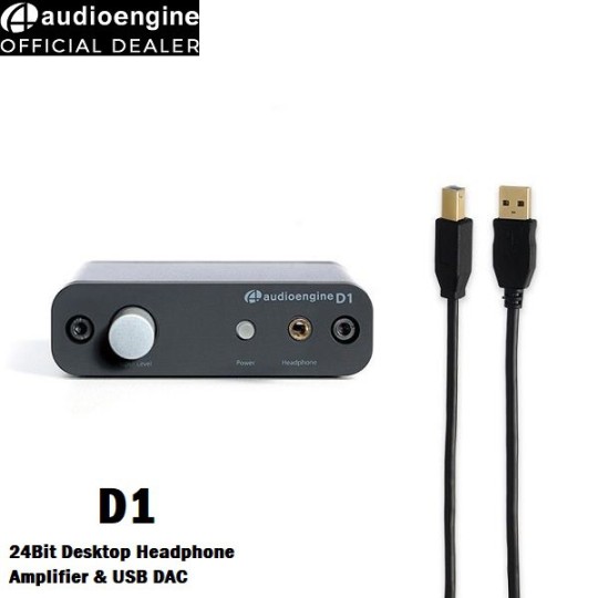
The D1 accepts inputs from both USB and optical and has outputs for any audio system or headphones. The D1 DAC is the perfect way to get great-sounding music not only from your computer but also from your TV, Apple TV, DVD/BluRay player or CD player. And since it's powered by USB, D1 is also a high-quality portable computer headphone amplifier.
DESIGNED FOR THE COMPUTER AUDIOPHILE
D1 will process digital audio at any bit depth up to 24 bits and any sample rate to 192KHz. With it's high signal-to-noise ratio and low distortion the D1 delivers sound quality generally heard only in more expensive DACs. The high-performance headphone output was designed for a wide range of headphones and will satisfy even the most demanding headphone enthusiasts. Drum library vol 1 zippyshare.
EASY SETUP
Setup is easy and no special software is needed, making D1 a true plug-and-play solution. The D1 outputs connect to any audio system or powered speakers, such as the Audioengine A5+ or A2. Power for the D1 is provided via the USB bus so there is no external power supply to connect.
D1 USB
The D1 utilizes the TI1020B USB controller, widely recognized as a standard for higher-end USB audio products. The D1 is powered directly from the USB bus and USB power is passed through two stages of regulation to ensure high stability and low noise.
D1 DAC
The D1 uses the AK4396 DAC, well regarded for its low noise and high fidelity. Due to the high signal-to-noise specs of the AK4396 and the added benefit of double redundancy power source conversion and filtering, the D1 presents impressive low noise and low distortion characteristics.
D1 HEADPHONE
Audioengine D1 Firmware
The D1 includes a headphone amp based on the TI OPA2134 low noise opamp. This headphone amp is able to provide low-impedance, high-fidelity audio to a wide range of headphones and supports headphones with impedance as low as 20 ohms.
0 notes
Link
HIFI Headphone Amplifier Circuit Diagram
This 1-watt amplifier leads itself par excellence for usa as driver for a low impedance headphone or as output stage in a hi-fi preamplifier driving an active loudspeaker. The schematic of this amplifier consists of an opamp type LF356 and a push-pull transistor output stage. Low-pass filter R1/C2 at the input limits the slew rateof the input signal. The fixed quiescent current of 30 mA draw by the output transistors, and set by diodes D1…D4 in conjuction with emitter resistors R7 and R8, ensures very low crossover distorsion.
HIFI Headphone Amplifier Circuit Diagram
Feedback resitors R3 and R4 fix the gain at about 15dB. The consequent overall distortion with a 3dB bandwidth from 10 Hz to 30 Hz is only 0.1 percent.
The amplifier delivers a maxiumum powder of 1 watt into 8 ohm for an input signal of about 500 mV rms. High-impedance headphones and 4 ohm loudspeakers may also be connected withoutdetriment.
The amplifier is best build on the printed circuit boar shonw bellow. The two transistors (BD139, BD140) shoud be mounted on heat sinks - do not forget the insulating washers and the head conducting paste!
To drive high-imperdance headphones at high volume, you need a +/- 15 volts regulated powder supply
Searches related to hifi headphone amplifier circuit diagramheadphone amplifier circuit using op-amp,simple headphone amplifier circuit,stereo headphone amplifier circuit,build your own headphone amp,ne5532 headphone amplifier circuit,how to make your own headphone amplifier,simple headphone circuits,headphone amplifier circuit design,
0 notes
Last Seen Blogs

thottedplant
heaux for nature

zodiac-info
Zodiac Info

magical-campanula
LOVE WILL KEEP US ALIVE

riflesquiddle
mrs strider!!!!!!!!!!!!

theoutdoordad
Father of Four