#Isometric drawing Guide
Text
Isometric Drawing Guide: Explained in 2024

Learn all about isometric drawing in 2024 with this comprehensive guide. Explore techniques, tips, and more. Isometric drawing is a method of graphic representation that allows for the visualization of three-dimensional structures on a two-dimensional plane.
This technique is particularly useful in the fields of architecture, engineering, and design, offering a clear and detailed view of an object from multiple perspectives without distorting the dimensions.
Unlike perspective drawing, which can appear more realistic but is complex to construct, isometric drawing simplifies the drawing process by maintaining a uniform scale in all directions, thus enabling easier interpretation and measurement directly from the drawing.
0 notes
Text
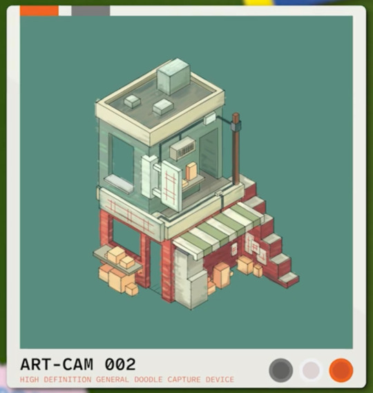
mumbo’s little concept art for his base is so cute i love it
#.lvblg#forgot to get a screenshot when i was up to him actually drawing it#ik he just used the isometric guide in procreate but the colours are very Pleasant#the vibes are immaculate#loving mumbo’s artist arc#then again videography/photography is an art form so. different flavour of artist arc
38 notes
·
View notes
Text
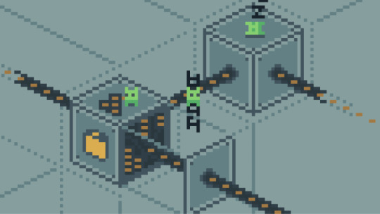
they tryin their damn best ⚡️
#the technical drawings I did for one of the in-game guide books for snacktorio are still some of my fav#and so wasted too like I did 7 of these bastards all in isometric#and you see them for like 5s#so damn right im gunna keep reposting them everywhere#game development#indie games#pixel art
11 notes
·
View notes
Photo
Infrastructure icon
0 notes
Text

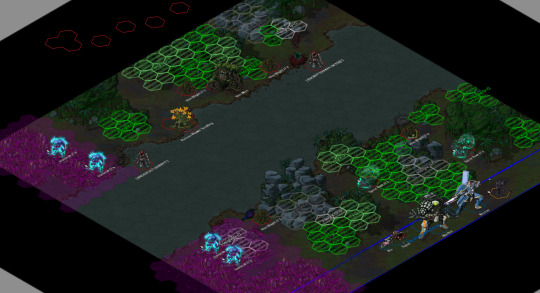

Tilesets used:
Starlight Furnace - Hercynian Lowlands
Lazarus - VTT Sci-Fi Tactical Map
On FoundryVTT, using Grapejuice Isometrics.
This week on Saturday lancer, the party began their dragon hunt on Caliburnus. They'd need to trek through the wilderness, using their skills to avoid riling up the forest too much while approaching their prey. They opted to take the river path, and ran into the Metal Men.
While previous Cynthia seemed to have made a good impression on them, at the sight of Ea (Ria's mech), they were sent into a frenzy and started attacking the party.
Mission deets under cut:
Mission // 005
Dragon Hunt
After the tense mission on Ulone Fortuna Wing decides to travel first to Cephus for vacation, and then to Caliburnus once Dandelion's curiosity of the oddities regarding Arianna's home become too much to bear. Caliburnus is an incredibly dangerous world, and simply leaving the settlement necessitates being in a mech suit lest one perishes.
Driven to seek answers, the party requests a chance to hunt a dragon as Arianna has mentioned them before, and Maeve grants them the right—but no more than that—to drive off Tiarna Dóiteáin who has nested close enough to be a risk. Arianna hopes to speak with the other Cursed Ones in order to find why Ea has gone silent, but before that they must succeed in hunting the Lord of Fire…
Goals
Find the Lord of Fire's resting place.
Drive the "dragon" off.
Enemy OPFOR
Wildly varied local flora and fauna, likely primarily biological units.
Though the locals and Arianna are familiar with the wildlife, that does not necessarily translate into Scan-quality knowledge.
Potential encounters include: Metal Men, Centaurus, Ironbeaks, Steel Crackers, Furnace Flowers, Shambling Trees, Vine Men, Luring Snappers, Rolling Clickers, Web Swarmers, Strangling Waters, Living Flames, Moving Forests, and Dragon Scales.
Reserves
Environmental shielding (On Ria)
Boosted Servos
Access
Knowledge
Special Conditions
Living World: At the start of every Round, roll 1d6. On 4+, the location of every character that moved last Round is targeted by "Living Thorns", which activate at the end of the current Round.
Choking Miasma: Areas around fungal terrain count as Hard Cover, but units within them cannot draw Line of Sight outside of them. These areas are designated by Purple measurement templates.
Hostile Flora: Ending a turn in soft cover granted by plants deals 1 AP Kinetic damage. Any attempt to clear out plant-based soft cover must deal a minimum of 5 damage in a single attack, otherwise the cover is unaffected. Fire/fire-effects from attacks or abilities do not spread, unless explicitly stated by it.
River Path
The Great Tree that Làirig Dhrù rests upon condenses much of the local rainfall, converting it into flowing rivers leading down. Following this flow allows for quick traversal, assuming you're willing to risk the dangers involved.
Primary Objective: Defeat all enemy units.
Secondary Objective // 1: Allow a Metal Man to summon a Moving Forest, then defeat it. (0/1)
Reward: x1 CORE battery
As a rule, even the most hostile of flora seem to respect the Metal Men. Likely due to their inedible nature, and tendency to care for them.
Special Conditions
Torus: Moving into one of the Torus's hexes immediately causes that unit to be randomly teleported to one of the other Torus hexes.
Enemy comp for this map includes:
Metal Men, who are Tokolosh (Field Guide to Mfecane) Veterans with a special ability to affect both Biological units with tech attacks and spend a Full Action to summon Reinforcements. Their gimmick is to Lure players out of hiding, slap them with Death Clock to force a player to maintain Danger Zone. This combos with—
Ironbeaks, who are Nosferatu (Lancer Enhanced Combat) that primarily hunt high heat targets. While not mandatory, I played them as predator animals mostly focused on hunting down high heat (both player and enemy), so they mostly hover out of combat and only swoop in when someone hits the Danger Zone. The Bite to absorb heat, then attack repeatedly with Talon once exposed. +Heat Seeking to make their targeting priorities clear. Slightly customized with the Monstrosity's +Winged.
Furnace Flower Seedlings, who are Stormcallers (Field Guide to Liminal Space) with the Turret Template (Maximum Threat) +Fixed. Their job is to mostly be a long range nuisance on the other side of the river, forcing players to deal with them or slowly get burned and impaired.
Spear Roots, who are Monstrosities with +Natural Camouflage and +Burrower. They only activate when someone is within LOS and Sensors, and then will target whoever they think is the weakest. Mostly just a hassle.
Vine Blights, Monstrosity Grunts with the Revenant Template (Maximum Threat), whose gimmick is being able to survive dying once (unless overkilled enough to remove the wreckage). Low risk but demanding two actions across two Rounds to put down for good.
Vine Men, Barricades with the Horror Template (Dustgrave), but really just for a custom trait called +Living that turns them Biological. Comes with +Drag Down to be a threat to the team's Nelson.
Walking Forest, a Brute (Lancer Enhanced Combat) Veteran with a renamed +Grafted Weapon who job it is is to be a big scary meatshield.
Had to call it at the top of Round 4, we rolled Living Thorns going off every Round. Burst 4, attack roll for 4 AP Kinetic damage Hull Save vs Prone, miss halves damage and no Prone. Not supposed to be huge damage (and the attack roll means our Saladin's abilities can help reduce damage or risk), but makes a constant pressure on the players when it goes off. You can only ever be attacked by a single Living Thorn no matter how many aoes you are in.
7 notes
·
View notes
Text
CSP Guide Recs!
A series of guide assets that help if you struggle with composition or generally keeping your perspective accurate.
1. Equal to extension lines
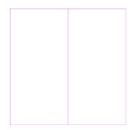
Evenly splits the screen however you need it to. Goes up to tenths.
2. ISOMETRIC TOOLS

Guideline set specifically for drawing isometric perspective.
3. Adaptive Gold Ratio Adaptive Golden Ratio
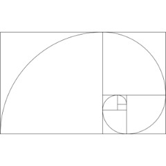
What it says on the box. Golden ratio guide that's resizeable based on your canvas.
4.〖Square 〗 12 different compositions
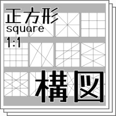
Another composition guide set. This one specifically is for square images.
5. Screen ratio ruler Variety
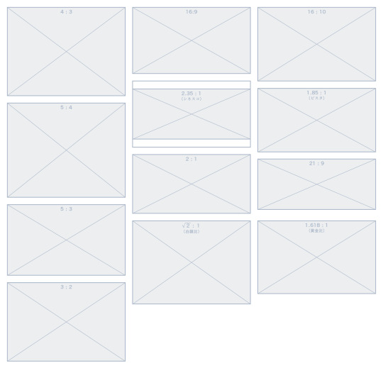
Pretty straightforward. Shows you the ratios of the most common screen formats.
47 notes
·
View notes
Text
Projection Surface Plan
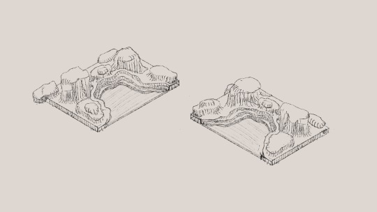
i used an isometric drawing guide to do some little sketches of what id like my bay to look like, it wont look like this exactly as it looks quite angular and flat but i want it to be more natural and flowy. i want to have a decent amount of surface area to project my animations onto but i also wanted it to have enough depth to be interesting when hanging vertical I plan to make this out of expanding foam as it means i can carve the shapes out of the foam once it dries and it also doesnt make it too heavy. i did initially think about doing this sculpture out of cardboard but it would take so much more effort rather than using expanding foam and having a chance of it looking much more natural and organic.
some bay inspiration


2 notes
·
View notes
Text
Week four: perspective sketches
This week our learning was about perspective sketching. This helps visualise a concept for how it would look in real life, projected onto a 2D page. There are a number of different types of perspective sketching such as one, two, and three point perspective, as well as isometric perspective drawing. Each have their uses and purposes, however the scale of objects that industrial designers focus on lends itself to using a 2 point perspective drawing.
Our first exercise was to translate a view of a chamfered box to a perspective view. This involved gathering measurement distances from where we viewed the box in real life in relation to our eyes. My view point was about 150 mm down and 300 mm away from my eyes. These measurements were used to set the distance from the ground line to the horizon line, and the picture plane to the station point. Once these lines were established I went about constructing my drawing.
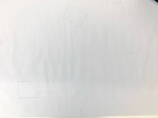
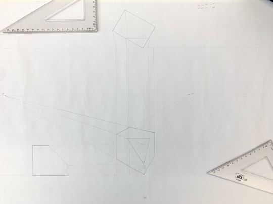
I realised that my first go didn’t look quite right, and I established that I had not referenced my vanishing points correctly. I had not properly followed the angle to the top of the PP line, then directly down to the HL (I had just gone straight from the ground line to the HL). This meant that my vanishing points were too close to the object to give the right perspective. I redrew my guides with the proper angles and vanishing point positions I fixed this my sketch came together.
I still don’t feel particularly confident in my understanding of all the different planes (HL, PP etc.) their names and different uses. However the more I construct accurate sketches the more I will become familiar with their functionality and usefulness.
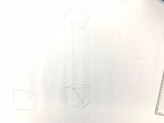
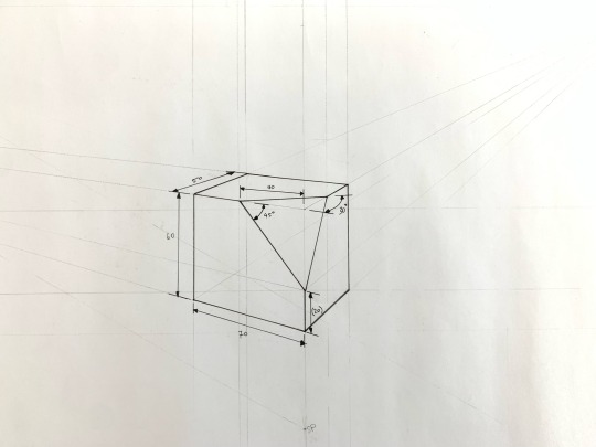
Adding boxes in the next exercise initially looked quite complicated — how do you establish the measurement points? I found using the centrepoint method to be a very neat and straightforward way of extending shapes in the desired direction. This is done by establishing the midpoint of the edge you wish to extend pass, and drawing an X extending from the corners below, through the midpoint, until they hit the vertical bounds of your box. This then gives the other corners with which you can establish a perspective box.
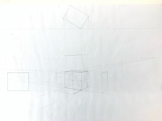
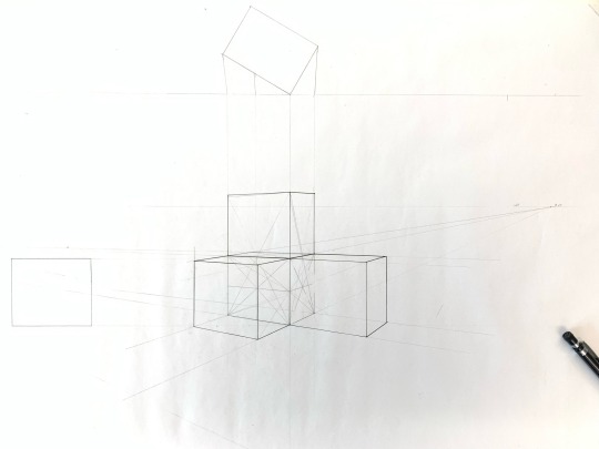
When it came to establishing ellipses on the faces of the cube, I found it difficult to draw nice curved lines. The end result was quite sketch like, and I’m wondering if anyone has a good technique to share to get a nicer drawing?
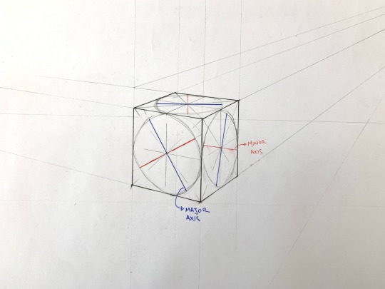
From this week’s exercises I feel a lot more comfortable establishing perspective sketches. I think adding a 30 degree rotation is an especially useful way of representing products and drawings. I think this will be useful for further sketching when representing other products to be able to set a global boundary, and hand sketch the designs within that.
I feel very confident drawing straight lines and angles to a high degree of accuracy, but my drawing of freehand curves still needs practice and improvement.
8 notes
·
View notes
Text
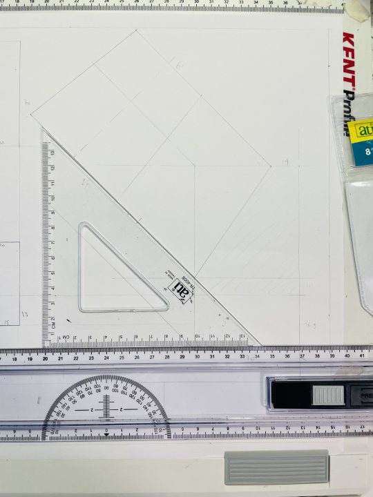
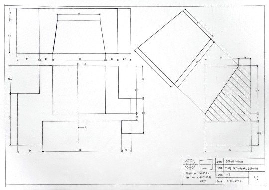
Week 3 – Section and Auxiliary Views
this week's focus is to learn about constructing an auxiliary view with the sections.
The drawing starts off with a draft drawing like what we have done last week.
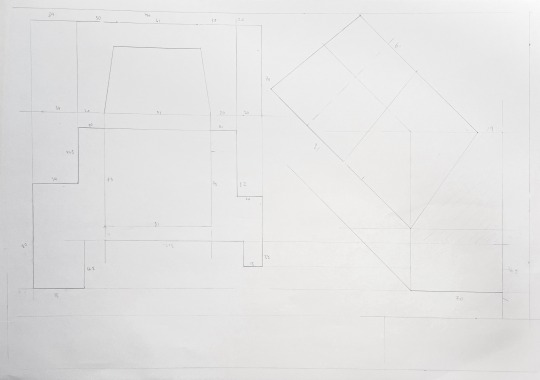
It starts with a given isometric view and generates the top and front view to help create the section of the right view. As the isometric was showing the drawing with the same base length as it is a parallel side view, I have misunderstood the front view with the same baseline other than a lifted base on the right. From this, I also acknowledged the importance of how different views are necessary for providing information for understanding an object's construction and dimensions.
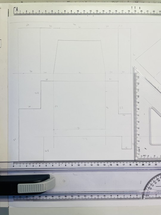
With accurate measurements of the front & top view, I have smoothly constructed the right section view. By examining the section side, the actual length of the hollow part of the object, the auxiliary view is drawn parallel to the section.
After the draft, I traced over the drawing on tracing paper with a pen. I have used two line weights (0.5, 0.2) to distinguish the back and front, up and down of the object. It is not really obvious on a hand-drawing and on the scanned picture, I could use a higher difference line weight on the next task.
And regarding using each view as the other's guide, the drawing is lined quite close to each other. It could be to space out the gap in between and make it more spacious. Overall it is a nice try for the week!
8 notes
·
View notes
Text


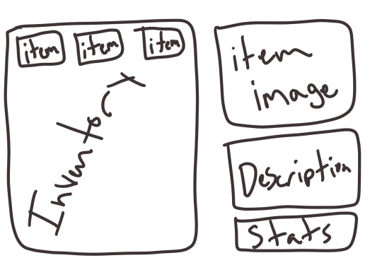
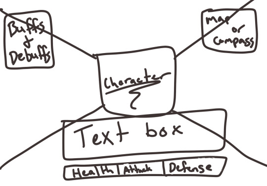

Here are some sketches i’ve made since i’ve gotten procreate on ipad!! this app was a great investment and has been so fun the play around with. the first two images are sketches of some sprites and character design i’ve done. then, the next two show the GUI layout for the main game when interacting with a character and the inventory layout!! the final sketch is of the title screen. this sketch is NOT final but was a chance to mess around with different brushes, isometric drawing guide, and a color pallet. i’ve decided on a different pallet (seen in the first image above) for the actual game. i’m so excited to continue working on the art and design!!
2 notes
·
View notes
Text
Types of Drawings Used in Design & Construction
Floor Plan Drawings: Illustrate the layout of rooms, walls, and features within a building.
Elevation Drawings: Provide a frontal view of a building's exterior, showing architectural details and proportions.
Section Drawings: Offer a vertical cut-through view of a building, revealing internal structure and components.
Site Plan Drawings: Depict the layout of a building or development within its surroundings, including land features and utilities.
Detail Drawings: Focus on specific components or assemblies within a building, showcasing construction methods and materials.
Perspective Drawings: Present a three-dimensional view of a building or space from a particular vantage point, enhancing visual communication.
Isometric Drawings: Display three-dimensional objects in a single view, emphasizing spatial relationships and proportions.
Sketches and Conceptual Drawings: Capture initial design ideas and concepts, exploring creative possibilities.
Working Drawings: Provide detailed information for construction, including dimensions, materials, and assembly instructions.
As-Built Drawings: Document the final built structure, incorporating any changes made during construction.
Presentation Drawings: Communicate design concepts and proposals to clients and stakeholders, often emphasizing aesthetics and visual appeal.
Technical Drawings: Convey precise measurements, specifications, and engineering details for manufacturing or construction.
CAD (Computer-Aided Design) Drawings: Utilize software to create accurate and detailed digital representations of architectural designs.
Structural Drawings: Focus on the structural elements of a building, including beams, columns, and foundations.
Architectural Drawings: Encompass various drawings related to architectural design, including plans, elevations, and details.
Mechanical Drawings: Detail mechanical systems and components within a building, such as HVAC and plumbing.
Electrical Drawings: Specify electrical systems, wiring diagrams, and equipment locations.
Plumbing Drawings: Outline plumbing systems, fixtures, and piping layouts within a building.
Landscape Drawings: Design outdoor spaces, including gardens, paths, and plantings, to complement the built environment.
Interior Design Drawings: Plan interior spaces, selecting finishes, furniture, and decorative elements.
Foundation Drawings: Detail the design and construction of building foundations, including footings and slabs.
Reinforcement Drawings: Specify the placement and configuration of reinforcing steel within concrete structures.
Roof Plan Drawings: Show the layout of roof elements, including slopes, ridges, and drainage systems.
Detailing Drawings: Provide enlarged views and annotations for intricate design or construction elements.
Schematic Drawings: Present simplified representations of systems or components, focusing on key connections and relationships.
Shop Drawings: Detail prefabricated components or custom-made items, including dimensions and material specifications.
Fabrication Drawings: Provide instructions for manufacturing components, including machining and assembly details.
Installation Drawings: Guide the installation of equipment or systems within a building, ensuring proper placement and alignment.
Network Drawings: Diagram the layout and connections of computer or communication networks, including cables and devices.
Piping and Instrumentation Drawings (P&ID): Illustrate process piping, instrumentation, and control systems within industrial facilities.
Control System Drawings: Specify the layout and components of control systems, including panels, sensors, and actuators.
HVAC (Heating, Ventilation, and Air Conditioning) Drawings: Design and layout HVAC systems, including ductwork, vents, and equipment.
Fire Protection Drawings: Outline fire suppression and detection systems, including sprinklers, alarms, and exits.
Security System Drawings: Specify the layout and components of security systems, including cameras, sensors, and access control.
Communication System Drawings: Design and document communication infrastructure, including cables, outlets, and equipment.
Lighting Drawings: Plan the placement and type of lighting fixtures within a building, including switches and controls.
Furniture Drawings: Specify the selection and arrangement of furniture within interior spaces, considering functionality and aesthetics.
Fixture Drawings: Detail built-in fixtures, such as sinks, cabinets, and shelving, within a building.
Casework Drawings: Specify the design and construction of custom-built cabinets, counters, and storage units.
Millwork Drawings: Detail architectural woodwork, including doors, moldings, and paneling, to enhance interior spaces.
Equipment Layout Drawings: Plan the placement and arrangement of equipment within industrial or commercial facilities, optimizing workflow and efficiency.
Demolition Drawings: Outline the removal and dismantling of existing structures or components, ensuring safety and efficiency during demolition processes.
These drawings serve as essential tools for architects, engineers, designers, contractors, and other stakeholders involved in the design and construction process, facilitating communication, coordination, and implementation of projects.United-BIM Inc. is a certified SBE/MBE BIM Modeling Services Company based in East Hartford, Connecticut. Our services include BIM Architectural Modeling, Architectural Drafting Services, 3D Rendering Services Structural Modeling and Detailing (Rebar, Precast, others), MEP-FP Modeling and Detailing, BIM Coordination & Clash Detection Services, Revit Family Creation Services, Underground Utility Locating Services, On-site & off-site Coordination Services, Onsite & virtual meetings participation, Point Cloud Scan to BIM, CAD to BIM Services, BIM for Facility Management, Accurate Shop Drawings Creation, As-built Drawings Services, Electrical Design Services & more.
0 notes
Text
Understanding the Importance of HVAC Drawings and Blueprints: A Comprehensive Guide

Table of Contents:
1.Importance of HVAC Drawings
2.Purpose of HVAC Blueprints
3.Understanding HVAC Systems
4.Types of HVAC Drawings
5.Reading HVAC Drawings & Blueprints
6.Creating HVAC Drawings
7.Tips for Efficient HVAC Drawing Creation
8.Reading & Analyzing HVAC Blueprints
9.Importance of Blueprints in HVAC Installation
10.How HVAC Drawings Improve Maintenance and Troubleshooting
11.Future Trends in HVAC Drawing and Blueprint Technology
12.Conclusion
Importance of HVAC Drawings
HVAC (Heating, Ventilation, and Air Conditioning) drawings are fundamental blueprints essential for the design, installation, and maintenance of HVAC systems in buildings. These drawings provide a visual representation of the HVAC system's layout, including ductwork, piping, equipment placement, and electrical connections. They serve as a crucial communication tool between architects, engineers, contractors, and technicians, ensuring that the HVAC system functions effectively and efficiently.
Purpose of HVAC Blueprints
HVAC blueprints serve multiple purposes throughout the lifecycle of a building. During the design phase, they help architects and engineers conceptualize the HVAC system's layout, ensuring optimal space utilization and compliance with building codes and regulations. During construction, blueprints guide contractors and technicians in the accurate installation of HVAC components, minimizing errors and rework. Additionally, these blueprints serve as reference documents for maintenance and troubleshooting tasks throughout the building's lifespan.
Understanding HVAC Systems
Before delving into the specifics of HVAC drawings and blueprints, it's essential to understand the components and principles of HVAC systems. HVAC systems are designed to control indoor temperature, humidity, and air quality to create a comfortable and healthy indoor environment. They typically comprise heating units (such as furnaces or boilers), ventilation systems (including ductwork and fans), air conditioning units, and controls for regulation.
Types of HVAC Drawings
HVAC drawings come in various types, each serving a specific purpose:
Floor Plans: Provide a bird's-eye view of the building layout, indicating the placement of HVAC equipment, vents, and ductwork.
Elevation Drawings: Offer vertical views of HVAC components, illustrating their height and position relative to other building features.
Sectional Drawings: Show cross-sectional views of HVAC systems, revealing internal details like ductwork and piping arrangements.
Schematics: Present simplified diagrams of HVAC systems, highlighting connections and flow paths for air and fluids.
Isometric Drawings: Provide 3D representations of HVAC components, offering a clearer understanding of spatial relationships and installation requirements.
Reading HVAC Drawings & Blueprints:
Proficiently interpreting HVAC drawings and blueprints is essential for architects, engineers, contractors, and technicians. It requires a thorough understanding of symbols, annotations, scales, and industry standards. Symbols represent various HVAC components, such as fans, dampers, valves, and thermostats, while annotations provide critical information like dimensions, materials, and performance specifications. Additionally, familiarity with scales ensures accurate measurement and placement of components within the building layout.
Creating HVAC Drawings
Creating HVAC drawings involves a collaborative effort among architects, engineers, and designers. Modern CAD (Computer-Aided Design) software facilitates the drafting process, allowing for precise modeling and documentation of HVAC systems. Designers input architectural plans and specifications into CAD software, where they can manipulate components, generate layouts, and produce detailed drawings with ease. CAD software also enables revisions and updates to accommodate changes in project requirements or building codes.
Tips for Efficient HVAC Drawing Creation:
To streamline the HVAC drawing creation process, consider the following tips:
Standardization: Establish standardized symbols, templates, and procedures to ensure consistency across drawings.
Clarity: Use clear and concise labeling, annotations, and legends to enhance readability and comprehension.
Accuracy: Double-check measurements, calculations, and specifications to minimize errors and discrepancies.
Collaboration: Foster open communication and collaboration among design team members to address potential conflicts or challenges early in the process.
Documentation: Maintain detailed records of revisions, approvals, and design decisions to track the evolution of HVAC drawings throughout the project lifecycle.
Reading & Analyzing HVAC Blueprints
When reading HVAC blueprints, it's essential to pay attention to key elements such as:
Equipment Placement: Identify the location of HVAC units, vents, registers, and exhaust fans to ensure optimal airflow and distribution.
Ductwork Layout: Analyze the routing and sizing of ductwork to minimize pressure drops and airflow restrictions.
Piping Configuration: Review the layout of piping systems for heating, cooling, and fluid distribution, ensuring proper insulation and support.
Electrical Connections: Verify the placement and wiring of electrical components, such as motors, controllers, and sensors, to ensure safe and efficient operation.
Importance of Blueprints in HVAC Installation
Accurate HVAC blueprints are critical for the successful installation of HVAC systems, as they provide precise instructions for contractors and technicians. By following the blueprints closely, installers can ensure that components are positioned correctly, connections are made accurately, and systems are commissioned properly. This adherence to the blueprint minimizes installation errors, reduces rework, and improves overall project efficiency and quality.
How HVAC Drawings Improve Maintenance and Troubleshooting
Throughout the lifecycle of a building, HVAC drawings play a vital role in maintenance and troubleshooting activities. Maintenance technicians rely on blueprints to locate equipment, access service points, and perform routine inspections and repairs efficiently. When troubleshooting HVAC issues, technicians can refer to drawings to identify potential sources of problems, such as duct leaks, valve malfunctions, or electrical faults, enabling quicker diagnosis and resolution.
Future Trends in HVAC Drawing and Blueprint Technology
The future of HVAC drawing and blueprint technology is marked by advancements in digitalization, automation, and integration. CAD software continues to evolve with features like 3D modeling, virtual reality (VR) simulation, and cloud collaboration, enhancing design visualization and communication. Building Information Modeling (BIM) platforms integrate HVAC drawings with other building systems, fostering greater coordination and efficiency throughout the construction process. Additionally, IoT (Internet of Things) sensors and AI (Artificial Intelligence) algorithms offer predictive maintenance capabilities, enabling proactive system monitoring and optimization.
Conclusion
In conclusion, HVAC drawings and blueprints are indispensable tools for the design, installation, and maintenance of HVAC systems in buildings. By providing detailed visual representations of system layouts, components, and connections, these drawings facilitate effective communication and collaboration among project stakeholders. Whether creating drawings from scratch or interpreting existing blueprints, architects, engineers, contractors, and technicians must possess the necessary skills and knowledge to ensure the successful implementation and operation of HVAC systems. As technology continues to advance, embracing digital tools and techniques will further enhance the efficiency, accuracy, and sustainability of HVAC drawing and blueprint processes.
#gsourcetechnologies#architecturedesigns#engineeringdesigns#cad services#hvacdrawings#caddrafting#hvacservices#hvacsolutions#draftingservices
1 note
·
View note
Video
youtube
Orthographic Isometric Drawing: A Comprehensive Guide Using LibreCAD 2D
1 note
·
View note
Photo

Legacy icon
1 note
·
View note
Text
Create Technical Drawing in FreeCAD
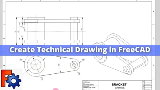
Hello friends welcome to FreeCAD tutorial in our previous tutorial we have learned Material Texture and Rendering in FreeCAD. In this tutorial we will learn Create Technical Drawing in FreeCAD.
Follow the step by step guide shown in the below video to Create Technical Drawing in FreeCAD. key points of Video are as follow.
- Introduction to FreeCAD Tutorial:
- The tutorial focuses on creating a technical drawing in FreeCAD using the Tech Draw workbench.
- The presenter mentions Mech Nexus, where articles and FreeCAD tutorials are available, along with the option to download tutorial source files.
- Template Insertion:
- The presenter activates the Tech Draw workbench and inserts a template from FreeCAD's template library, choosing the A3 template in English.
- Explains how to edit the title block fields, including the title, subtitles, company name, scale, check date, supervision date, and author.
- Base View Setup:
- Demonstrates setting the base view for the model, selecting the front, top, and side views using the "insert projection group" option.
- Highlights the importance of using projection groups for maintaining association between views.
- Isometric View Insertion:
- Adjusts the scale in the page properties and inserts an isometric view using the "insert view" option, providing an alternative method to projection groups.
- Shows how to toggle the visibility of borders around views.
- Detailing Process:
- Covers the addition of center marks and center lines, followed by detailing steps such as providing dimensions for arcs, angles, and distances.
- Illustrates the process of defining dimensions for plates, internal features, and circular parts to complete the technical drawing.
https://www.youtube.com/watch?v=aqPgIn8auig&ab_channel=Mechnexus
“Thank you for reading! If you found this article insightful and valuable, consider sharing it with your friends and followers on social media. Your share can help others discover this content too. Let’s spread knowledge together. Your support is greatly appreciated!”
Read the full article
0 notes
Text
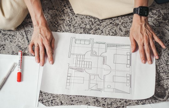
How to Start Isometric Drawing in AutoCAD
Isometric drawing is a valuable skill for anyone working in fields like engineering, architecture, or design. It allows you to create three-dimensional representations of objects with ease and precision. AutoCAD, a popular computer-aided design software, offers powerful tools for creating isometric drawings. In this article, we'll guide you through the process of getting started with isometric drawing in AutoCAD.
Understanding Isometric Drawing
Before diving into the practical aspects, it's essential to grasp the concept of isometric drawing. In simple terms, isometric drawing is a method of representing a three-dimensional object on a two-dimensional surface. Unlike traditional 2D drawings, isometric drawings provide a realistic perspective, making it easier to visualize complex structures.
Benefits of Isometric Drawing
Enhanced Visualization: Isometric drawings give a more realistic view of your designs, making it easier to identify potential issues and improvements.
Accurate Measurements: It allow for precise measurements and calculations, critical in engineering and construction.
Improved Communication: Isometric drawings are universally understood, making them an effective way to convey your ideas to others.
Setting up AutoCAD for Isometric Drawing
Before you start creating isometric drawings in AutoCAD, you need to configure the software for this specific purpose.
Step 1: Open AutoCAD
Launch AutoCAD on your computer, and ensure you have a new drawing or an existing one ready to work on.
Step 2: Set Units
Go to the "Units" command and ensure your units are set correctly. Isometric drawings often use metric or imperial units, depending on your project's requirements.
Step 3: Enable Isometric Snap
Type "SNAPSTYL" in the command line and set it to "Isometric."
Step 4: Set Isoplane
Use the "ISOPLANE" command to set your drawing plane to isometric. AutoCAD offers three isoplanes: top, right, and left. Choose the one that suits your needs.
Creating Isometric Drawings
With AutoCAD properly configured, you can now start creating isometric drawings.
Step 1: Draw Basic Shapes
Begin by drawing the basic shapes of your object. Use commands like "LINE," "CIRCLE," and "RECTANGLE" to create the framework.
Step 2: Use Isometric Snap
Ensure that your cursor snaps to the isometric gridlines. This helps maintain the correct angles and alignment.
Step 3: Extrude Shapes
To give your drawings depth, use the "EXTRUDE" command to turn 2D shapes into 3D objects. Specify the height or extrusion value as needed.
Step 4: Modify and Refine
AutoCAD offers various editing tools to modify your isometric drawings. Use commands like "MOVE," "ROTATE," and "SCALE" to make adjustments.

Tips for Isometric Drawing
Practice Regularly: Isometric drawing can be challenging at first, but consistent practice will improve your skills.
Use Layers: Organize your drawings using layers to make it easier to manage and edit individual elements.
Keyboard Shortcuts: Learn and use AutoCAD keyboard shortcuts to streamline your workflow.
FAQs (Frequently Asked Questions)
What is the main advantage of isometric drawing in AutoCAD?
Isometric drawings provide a more realistic view of objects, making it easier to understand complex designs.
Do I need prior experience in AutoCAD to start isometric drawing?
While some familiarity with AutoCAD is helpful, this article provides a beginner-friendly guide to get you started.
Can I create isometric drawings for both metric and imperial units in AutoCAD?
Yes, AutoCAD allows you to work with both metric and imperial units, depending on your project's requirements.
Are there any AutoCAD plugins or add-ons that can enhance isometric drawing capabilities? Yes, there are several plugins and add-ons available for AutoCAD that can simplify the process of creating isometric drawings.
Where can I find additional resources to improve my isometric drawing skills in AutoCAD? You can explore online tutorials, forums, and AutoCAD documentation to further enhance your isometric drawing skills.
Incorporating isometric drawing into your AutoCAD repertoire will undoubtedly enhance your ability to create precise and visually appealing designs. So, start practicing and exploring the creative possibilities that isometric drawing offers!
Absolutely, let's continue with more information on advanced techniques and additional resources for mastering isometric drawing in AutoCAD.

Advanced Techniques in Isometric Drawing
Once you've got the basics down, you can delve into more advanced techniques to take your isometric drawing skills to the next level.
1. Isometric Circles and Arcs
Drawing perfect circles and arcs in isometric projection can be tricky. AutoCAD offers commands like "ELLIPSE" and "ARC" to create these shapes accurately. Practice using these commands to add curved elements to your drawings.
2. 3D Models and Renderings
AutoCAD allows you to create detailed 3D models and renderings of your isometric drawings. You can apply materials, textures, and lighting effects to make your designs appear even more realistic.
3. Isometric Text and Dimensions
Incorporate text and dimensions into your drawings to provide important information. AutoCAD provides tools like "MTEXT" and "DIMENSION" for this purpose. Ensure that your text and dimensions align with the isometric grid.
4. Hatching and Fills
Use hatching and fills to distinguish different materials or areas within your isometric drawings. This helps in conveying information effectively.
Additional Resources
To further enhance your isometric drawing skills in AutoCAD, you can explore the following resources:
1. AutoCAD Tutorials
AutoCAD offers a wide range of tutorials on their official website. These tutorials cover various aspects of the software, including isometric drawing techniques.
2. Online Courses
Numerous online platforms offer courses specifically tailored to AutoCAD and isometric drawing. Websites like Coursera, Udemy, and LinkedIn Learning have courses for all skill levels.
3. Community Forums
Joining AutoCAD user forums and communities can be invaluable. You can ask questions, share your work, and learn from experienced users. Websites like Autodesk's own community forum are excellent places to start.
4. YouTube Tutorials
YouTube is a treasure trove of AutoCAD tutorials. Many skilled AutoCAD users create video tutorials that walk you through various aspects of the software, including isometric drawing techniques.
5. AutoCAD Documentation
Don't forget to explore AutoCAD's official documentation. It provides in-depth information on features, commands, and best practices.
Conclusion
Isometric drawing in AutoCAD is a valuable skill that can open up numerous opportunities in various industries. Whether you're an architect, engineer, or designer, mastering isometric drawing can significantly enhance your ability to communicate and visualize complex ideas.
Start your journey into the world of isometric drawing in AutoCAD today. With dedication, practice, and the right resources, you can become proficient in creating stunning, three-dimensional representations of your designs. Happy drawing!
Isometric drawing in AutoCAD opens up a world of possibilities for designers and engineers. It allows you to create detailed and realistic representations of objects and structures. By following the steps outlined in this article and practicing regularly, you'll master the art of isometric drawing in AutoCAD in no time.
You Read More blogs on AutoCAD India's Blog
0 notes
Last Seen Blogs

largando
Untitled

twentyyearstoolate
"Aren't you a little old for a shitposter?"

spf92bb
Secours Populaire Français Boulogne-Billancourt

violetisderp
VioletIsDerp
largando
Untitled