#FEA Consulting Engineers
Text
TEFUGEN: Redefining Engineering Excellence through Finite Element Analysis

WHY USE FEA IN YOUR ENGINEERING PROJECTS?
At the forefront of engineering excellence, TEFUGEN offers exceptional Finite Element Analysis (FEA) services in India. Utilizing FEA yields unparalleled benefits, offering profound insights into your project's performance prior to physical model construction. It aids in pinpointing stress points, identifying potential weaknesses, and assessing material durability under diverse conditions, effectively mitigating the risk of failure and associated costs. With its ability to conduct precise simulations, FEA empowers informed decision-making in design modifications, guaranteeing optimal performance and safety.
Structural Integrity Assessment:
In engineering, FEA, an indispensable method, meticulously assesses structural integrity by simulating material responses to diverse conditions. This predictive analysis is pivotal for guaranteeing the safety and reliability of designs. TEFUGEN, as a FEA consulting service in India, provides expert assistance, enabling engineers to identify potential weaknesses and optimize for durability.
Thermal stress analysis:
FEA analysis services play a key role in assessing heat distribution within structures or components. Engineers leverage this analysis to model and analyze thermal behavior meticulously. By doing so, they optimize designs for efficient heat dissipation or retention, ensuring the performance and reliability of the system. This detailed analysis enables engineers to make informed decisions regarding material selection, insulation, or heat management strategies, ultimately enhancing overall system efficiency and longevity.
Mechanical Component Design:
FE Analysis plays a crucial role in optimizing mechanical component design by accurately predicting stress, strain, and deformation. This ensures components can effectively withstand operational loads while minimizing material usage, thereby enhancing efficiency and cost-effectiveness.
Fatigue Analysis:
Engineers use FEA for fatigue analysis, predicting the lifespan of components subjected to cyclic loading. This is crucial in industries like aerospace and automotive, where understanding material fatigue is paramount.
Fluid Structure Interaction:
Fluid Structure Interaction (FSI) is a crucial aspect of FE Analysis, examining the dynamic interaction between fluids and structures. By simulating how fluids affect nearby structures and vice versa, FSI enables engineers to optimize designs for enhanced performance and durability across various industries.
Modal analysis
Modal analysis using FEA techniques enables the simulation of eigenfrequencies and eigenmodes, revealing the vibrational characteristics of a structure. Meanwhile, harmonic analysis facilitates the emulation of peak responses to specific loads, offering insights into system behavior. These analyses are indispensable tools for understanding structural dynamics and optimizing performance.
Motion study
Unlocking insights into structural behavior through Finite Element Analysis (FEA) motion studies.
Discover the intricate dynamics of systems, optimize designs, and ensure structural resilience with FEA motion analysis.
#Finite Element Analysis Consulting Services in India#FEA Analysis Services#FEA Consulting Engineers#FEA Consultants in Trichy#FEA#Finite Element Method#Structural Analysis#Stress Analysis#Static Analysis#Dynamic Analysis#Thermal Analysis#Fluid Flow Analysis#Vibration Analysis#Fatigue Analysis#Buckling Analysis#Modal Analysis#Meshing#Boundary Conditions#Material Properties#Convergence#Post-processing#Optimisation#Mesh Generation#Simulation Software
0 notes
Text
Fea Dynamics Analysis
Fea Fatigue Analysis
https://3d-labs.com/fea-services/
Comprehensive FEA Services for Enhanced Engineering Design and Analysis
3d-labs is an engineering consulting firm that provides full analysis using state-of-the-art FEA ,
CFD, and CAD/CAE tools. We help our clients reduce product development costs, decrease
time-to-market , and improve product quality. We, offer not only reliable analysis results but
also insight solutions to clients' projects….. We are from all sectors of the industry and have
excellent analytical skills and knowledge. We have co-operation with universities, national
laboratories, and other engineering firms, which enable us to address and solve clients'
questions and problems simply and quickly. We solve a broad range of engineering
analysis problems based on FEA techniques including stress analysis, fluid dynamics,
kinematics, heat transfer, dynamics and vibration (seismic, harmonic), structural
dynamics and electromagnetics. etc.
Introduction
Why Should we do Analysis
Elastic Stress Analysis Method
static Structural Analysis
Engineering Data
Geometry
Model
Setup
Solution
Results
Fatigue Analysis
Fatigue Tool
Solution
Results

0 notes
Text
Ananka
Q1. How do you assess the impact of vibration on hex bolt performance?
Assessing the impact of vibration on hex bolt performance involves evaluating the potential effects of vibrational forces on the bolted connection. Here's a systematic approach to understanding and mitigating the impact of vibration on hex bolt performance:
1. Identify Vibration Sources: Determine the sources of vibration within the system. Vibration can result from machinery, equipment, environmental factors, or operational conditions.
2. Frequency Analysis: Analyse the frequency of vibration. Different frequencies can induce various effects on bolted connections, such as resonance or fatigue.
3. Dynamic Load Calculation: Calculate the dynamic load applied to the bolt due to vibration. Dynamic loads can significantly exceed static loads and may cause bolt loosening or failure.
4. Thread Lubrication: Properly lubricate bolt threads to reduce friction and prevent self-loosening caused by vibration-induced micro-movements.
5. Locking Mechanisms: Implement locking mechanisms like locking nuts, lock washers, or thread-locking compounds. These devices introduce additional friction to counteract vibrational forces.
6. Preload Optimization: Apply appropriate preload to the bolt. Adequate preload helps maintain clamp load even in the presence of vibrational forces.
7. Thread Engagement: Ensure sufficient thread engagement between the bolt and nut. Insufficient engagement might lead to premature bolt failure under vibration.
8. Elasticity of Materials: Choose materials with suitable elasticity. Flexible materials can better absorb vibrational forces without compromising the integrity of the bolted connection.
9. Fatigue Resistance: Select bolts with high fatigue resistance. Vibrational loads can induce fatigue failure over time, so fatigue-resistant bolts are better suited for such conditions.
10. Torque-Tension Relationship: Understand the torque-tension relationship. Applying proper torque ensures the desired clamp load for vibration resistance.
11. Locking Features: Opt for bolts with built-in locking features, such as serrated flanges or prevailing torque nuts. These features enhance resistance to self-loosening.
12. Thread Pitch: Consider using finer thread pitches. Fine threads distribute load more evenly and are less prone to self-loosening under vibration.
13. Inspection and Maintenance: Regularly inspect bolted connections for signs of loosening or damage due to vibration. Timely maintenance can prevent failures.
14. Finite Element Analysis (FEA): Employ FEA simulations to predict how different bolt materials, sizes, and configurations respond to specific vibrational loads.
15. Professional Consultation: If unsure about the impact of vibration on bolt performance, consult with engineering experts or professionals with experience in fastening and vibration analysis.
In summary, assessing the impact of vibration on hex bolt performance requires a thorough understanding of the vibration sources, load dynamics, and bolt behaviour. Implementing strategies like thread lubrication, locking mechanisms, preload optimization, and proper material selection can help mitigate the negative effects of vibration on bolted connections.
Q2. How do you address the challenges of using hex nuts in high-temperature environments?
Addressing the challenges of using hex nuts in high-temperature environments requires a thoughtful and strategic approach to ensure the nuts maintain their integrity and performance under elevated temperatures. Here's a step-by-step guide to effectively manage these challenges:
1. Material Selection: Opt for heat-resistant materials when choosing hex nuts. Consider alloys like stainless steel, nickel alloys, or other heat-resistant materials that can withstand the specific temperature range of the environment.
2. Temperature Limits: Determine the maximum temperature the hex nuts will be exposed to. Ensure that the selected materials are rated for temperatures exceeding those in your application.
3. Coatings and Treatments: Explore coatings or treatments that enhance the heat resistance of the hex nuts. Thermal barrier coatings, ceramic coatings, or specialized high-temperature coatings can provide an extra layer of protection.
4. Thermal Expansion and Contraction: Account for thermal expansion and contraction of both the nut and bolt materials. Choose materials with similar coefficients of thermal expansion to minimize the risk of loosening due to differential expansion.
5. Tightening Procedures: Follow precise and manufacturer-recommended tightening procedures. High temperatures can affect torque and tension values, so ensure you're using the appropriate specifications for the elevated environment.
6. Insulation and Shields: Implement insulation materials or shields to create a barrier between the high-temperature environment and the hex nuts. This can help reduce direct heat transfer and maintain nut integrity.
7. Locking Mechanisms: Consider using specialized locking mechanisms designed for high-temperature applications. All-metal self-locking nuts, prevailing torque lock nuts, or other high-temperature locking solutions can prevent self-loosening.
8. Regular Inspection: Establish a regular inspection schedule for hex nuts in high-temperature environments. Look for signs of wear, deformation, or degradation caused by prolonged exposure to heat.
9. Thermal Cycling: If the environment involves temperature cycling, ensure the hex nuts can withstand repeated thermal expansion and contraction without compromising their functionality.
10. Expert Consultation: Seek advice from experts or engineers experienced in high-temperature applications. They can provide valuable insights into suitable materials, coatings, and locking mechanisms.
11. Testing and Validation: Consider performing tests or simulations to validate the performance of hex nuts in high-temperature conditions. This can help ensure their reliability and longevity.
12. Documentation: Develop clear documentation outlining procedures for nut selection, installation, maintenance, and replacement in high-temperature settings. This promotes consistency and proper practices.
13. Emergency Plans: Have contingency plans in place for addressing unexpected issues or failures. Be prepared to swiftly replace or address nuts that may become compromised in the high-temperature environment.
14. Continuous Monitoring: Implement a system for ongoing monitoring of hex nuts in high-temperature applications. This can help identify potential problems early and prevent catastrophic failures.
15. Training and Education: Ensure that personnel working with hex nuts in high-temperature environments are well-trained in the unique challenges and best practices associated with these conditions.
By following these steps and considering the specific demands of your high-temperature environment, you can effectively manage the challenges of using hex nuts and maintain the integrity of your bolted connections.
Q3. Can plain washers be used in situations requiring resistance to radiation?
Plain washers are typically not recommended for situations requiring resistance to radiation, especially in environments where radiation exposure is a significant concern. Radiation-resistant applications often involve conditions such as nuclear facilities, medical equipment utilizing ionizing radiation, space exploration, and certain scientific research settings.
Plain washers are generally made from common materials like steel, stainless steel, or non-metallic materials, which may not provide sufficient radiation resistance. Ionizing radiation, such as gamma rays and high-energy particles, can interact with materials and lead to degradation, weakening, or other undesirable effects.
In situations involving radiation resistance, specialized materials and components are chosen to withstand the specific radiation environment. These materials may include certain types of metals, ceramics, polymers, and composites that have been specifically engineered to resist radiation damage.
If you're dealing with applications where radiation resistance is a requirement, it's advisable to consult with radiation protection experts, engineers, or professionals experienced in working with radiation-resistant materials. They can guide you in selecting the appropriate components, including washers, that meet the necessary radiation resistance criteria for your specific application.
Q4. What is the significance of chamfered ends on stud bolts?
Chamfered ends on stud bolts serve several significant purposes in various applications, especially when these bolts are used in specific types of assemblies. A chamfer is a beveled or angled edge that is typically added to the ends of the bolt threads. Here are some key reasons for incorporating chamfered ends on stud bolts:
1. Ease of Installation: Chamfered ends make it easier to start the stud bolt into the threaded hole or nut. The chamfer guides the bolt smoothly into the threads, reducing the chances of cross-threading and facilitating a smoother installation process.
2. Alignment: Chamfered ends aid in aligning the stud bolt with the threaded hole or nut. This alignment ensures that the bolt enters the threads accurately and minimizes the risk of damaging the threads during installation.
3. Reduced Damage: Without chamfered ends, the abrupt end of the bolt can lead to localized stress concentrations, which might cause damage to the bolt or the threads of the hole or nut. Chamfering distributes stress more evenly, reducing the likelihood of damage.
4. Thread Protection: Chamfered ends can protect the first few threads from potential damage during handling, shipping, and installation. This is particularly important in environments where debris, dirt, or other contaminants could affect the threads.
5. Torque Application: Chamfered ends allow for smoother and more consistent torque application during tightening. This helps ensure accurate and uniform clamping force across the joint.
6. Reduced Stress Concentration: Sharp edges can act as stress concentrators, increasing the risk of fatigue and failure. Chamfering the ends helps to eliminate sharp edges and reduce stress concentrations.
7. Safety: Properly chamfered ends decrease the chances of cuts, scratches, or injuries to personnel during the handling and installation of stud bolts.
8. Improved Thread Engagement: By guiding the bolt into the threads, chamfered ends improve initial thread engagement, which is crucial for maintaining the integrity of the bolted joint.
9. Consistency: Chamfering ensures that the threads start from a consistent point on each bolt, leading to more uniform performance in threaded connections.
10. Aesthetics: Chamfered ends can improve the overall appearance of the bolted joint, providing a more finished and professional look.
It's important to note that the degree of chamfer and its dimensions can vary based on the specific application and requirements. Chamfers are particularly common in applications where stud bolts are used to connect components, such as flanges in piping systems, where accurate alignment and smooth installation are crucial for creating leak-free connections.
0 notes
Text
Mechanical Engineering Consultants
Prominent Features of Reputable Mechanical Engineering Companies
Mechanical engineering companies and consultants play a pivotal role in various industries by providing expertise in designing, analyzing, and implementing mechanical systems and solutions. Their services encompass a wide range of activities.
Mechanical engineering companies and consultants are essential players in driving innovation, efficiency, and progress across industries. The prominent features of a reputed and reliable mechanical engineering consultant or company are crucial for driving innovation, efficiency, and progress in diverse sectors. Some of these are here under:
Expertise and Specialization:
Mechanical engineering companies and consultants are staffed with professionals with in-depth knowledge and specialized skills in product design, manufacturing processes, thermal analysis, fluid dynamics, and more. Their expertise allows them to tackle complex challenges and provide solutions tailored to client needs.
Product Design and Development:
Product design and development are one of the core functions of mechanical engineering firms. They conceptualize, design, and prototype mechanical components, systems, and products from consumer goods to industrial machinery. These designs emphasize functionality, reliability, and manufacturability and often incorporate innovative features.
Simulation and Analysis:
Mechanical engineering consultants utilize advanced simulation and analysis tools to assess the performance of products and systems under different conditions. They conduct finite element analysis (FEA), computational fluid dynamics (CFD), and other simulations to predict mechanical components' behaviour, ensuring they meet safety and performance requirements before physical prototyping.
Prototyping and Testing:
Mechanical engineering firms often create prototypes of products or systems to validate their designs. They conduct testing to identify potential flaws, weaknesses, or areas for improvement. This iterative process helps refine designs and ensures final products meet or exceed expectations.

Innovation and R&D:
Mechanical engineering consultants contribute to research and development efforts to introduce new technologies, materials, and processes. They work at the forefront of innovation to create novel solutions that drive industry advancement.
Sustainability and Energy Efficiency:
In today's environmentally conscious landscape, mechanical engineering companies significantly design energy-efficient and sustainable solutions. They integrate practices that reduce resource consumption, minimize waste, and optimize energy usage in mechanical systems.
Multi-Disciplinary Collaboration:
Mechanical engineering often intersects with other disciplines, such as electrical engineering, software engineering, and materials science. These companies collaborate with experts from various fields to develop integrated solutions that require expertise beyond traditional mechanical engineering.
Project Management:
Mechanical engineering consultants manage projects from inception to completion. They handle timelines, budgets, resource allocation, and coordination of various stakeholders to ensure projects are delivered on time and within scope.
Consulting and Problem Solving:
Many mechanical engineering firms offer consulting services where they assist clients in resolving technical challenges, optimizing processes, and making informed decisions about product development, manufacturing, and system implementation.
0 notes
Text
Projected Boom in the Computer-Aided Engineering Market: On Track to Reach $12.67 Billion by 2027 at a CAGR of 9.2% || Altair Engineering Inc., Dassault Systèmes SE, ESI Group

The Computer Aided Engineering Global Market Report 2023, provides comprehensive information on the computer aided engineering market across 60+ geographies in the seven regions - Asia-Pacific, Western Europe, Eastern Europe, North America, South America, Middle East, Africa for the 27 major global industries. The report covers a ten year historic period – 2010-2021, and a ten year forecast period – 2023-2032.
Learn More On The Computer Aided Engineering Market’s Growth:https://www.thebusinessresearchcompany.com/report/computer-aided-engineering-global-market-report
As per The Business Research Company’s Computer Aided Engineering Global Market Report 2023, the global computer-aided engineering market size is expected to grow from $8.11 billion in 2022 to $8.90 billion in 2023 at a compound annual growth rate (CAGR) of 9.8%. The Russia-Ukraine war disrupted the chances of global economic recovery from the COVID-19 pandemic, at least in the short term. The war between these two countries has led to economic sanctions on multiple countries, a surge in commodity prices, and supply chain disruptions, causing inflation across goods and services and affecting many markets across the globe. The computer-aided engineering market size is expected to grow to $12.67 billion in 2027 at a CAGR of 9.2%.
Get A Free Sample Of The Report (Includes Graphs And Tables):https://www.thebusinessresearchcompany.com/sample.aspx?id=7941&type=smp
The computer aided engineering market is segmented:
1) By Type: Finite Element Analysis (FEA), Computational Fluid Dynamics (CFD), Multibody Dynamics, Optimization, and Simulation
2) By Deployment: On-Premise, Cloud-Based
3) By End-Use: Automotive, Defense and Aerospace, Electronics, Medical Devices, Industrial Equipment.
Europe was the largest region in the computer aided engineering market in 2022.
The table of contents in TBRC’s computer aided engineering market report includes:1. Executive Summary
2. Computer Aided Engineering Market Characteristics
3. Computer Aided Engineering Market Trends And Strategies
4. Computer Aided Engineering Market - Macro Economic Scenario
5. Computer Aided Engineering Market Size And Growth
……....
28. Key Mergers And Acquisitions In The Computer Aided Engineering Market
29. Computer Aided Engineering Market Future Outlook and Potential Analysis
30. Appendix
Learn About Us:
The Business Research Company is a market intelligence firm that pioneers in market, company, and consumer research. TBRC’s specialist consultants are located globally and are experts in a wide range of industries that include healthcare, manufacturing, financial services, chemicals, and technology, with 6500+ reports. The firm has offices located in the UK, the US, and India, along with a network of proficient researchers in 28 countries. Through the report businesses can gain a thorough understanding of the market’s size, growth rate, major drivers and leading players.
Contact Us:
The Business Research Company
Europe: +44 207 1930 708
Asia: +91 88972 63534
Americas: +1 315 623 0293
Email: [email protected]
Follow Us On:
LinkedIn: https://in.linkedin.com/company/the-business-research-company
Twitter: https://twitter.com/tbrc_info
Facebook: https://www.facebook.com/TheBusinessResearchCompany
YouTube: https://www.youtube.com/channel/UC24_fI0rV8cR5DxlCpgmyFQ
Blog: https://blog.tbrc.info/
Healthcare Blog: https://healthcareresearchreports.com/
Global Market Model: https://www.thebusinessresearchcompany.com/global-market-model
0 notes
Text
Exploring Tefugen's FEA Capabilities: Harnessing Advanced Analysis Techniques
FEA is a computer application that uses numerical techniques to assess systems and structures. When subjected to thermal and structural loads, it accurately predicts how components will react. Instead of needing to construct the actual component, using a virtual computer-based model makes it easier to check the design and integrity of a component and pinpoint important areas for development. TEFUGEN offers exceptional FEA analysis and consultancy services to help with simulation-based structural and thermal evaluation of mechanical systems.
In the field of engineering design, Finite Element Analysis (FEA) has developed into a highly promising computer-aided engineering technique for modeling and analyzing structures with complex geometries and changeable material properties. It is commonly used during the design phase of a range of engineering fields, such as automotive, aerospace, power plants, and production engineering, to optimize products that increase performance.
Advantages of FEA:
Minimize the product development cost
Reduce the product lead time into the market
Accurately predict components response to load
Unlimited level of detail in the system
Analyze difficult & dangerous experiments
Easy repeatability of simulation
Linear Analysis:
The branch of FEA known as linear static analysis is most typically used to evaluate the structural and thermal performance of mechanical structures. The applied forces and displacements have a linear connection in linear static analysis. Actually, where stresses remain within the material's linear elastic range, this is relevant to all structural components. In a linear static analysis, the model's stiffness matrix is constant, and the solving time is quicker than in a nonlinear analysis of the identical model. In order to obtain an initial estimate, linear static analysis is usually used before performing a full nonlinear analysis.
Static stress analysis is likely the most common type of structural analysis using the FE technique. Stress, strain, and deformation of a component or assembly can be assessed under various load scenarios to avoid expensive failures during the design stage.
Typically, structural loads consist of one or more of the following:
Outside forces, like the clamping force in subsea connectors.
Surface loads, such as the pressure inside pressure vessels
Body pressures (gravity, acceleration such as centrifugal force in rotating machines)
Dynamic Analysis :
The phrase "dynamic FEA" describes a number of dynamic simulation methods that can be used to analyze even complicated engineering systems. Dynamic analysis is used to design and analyze potential noise and vibration issues as well as to assess the effects of transient loads. As seasoned development engineers, we rarely end our involvement in a dynamic assessment with the analytical output. We frequently collaborate with customers to identify creative solutions that are practical and beneficial from a business standpoint.
Thermal Analysis :
Thermal analysis and FEA can be used to solve heat transmission in or between solids. Convection, conduction, and radiation are a few examples of heat transport mechanisms that can be calculated. However, the analyst directly estimates convection and radiation, not the FEA software. Heat transfer analysis with FEA is normally carried out when the heat convection coefficient can be assumed to be constant along the surface of the part or when the value is precisely known. FEA-based heat transfer analysis can also be used to determine structural stresses brought on by temperature gradients in the component, including thermal expansion.
Buckling Analysis:
By the use of buckling analysis, a structure's stability under compressive loading conditions is evaluated. To verify the stability of the construction, a weight-lifting device will need to be used under compressive loads. The kind of buckling analysis employed in FE analysis is called linear buckling analysis. A static structural study must be followed by a linear buckling analysis. The results of a linear buckling analysis are buckling load factors, which are scales of the loads employed in the static structural analysis. The structure will buckle when the aforementioned level of static loading is attained, according to the simulation's results. There are countless buckling load elements that might affect a building. Every load factor has a distinct instability pattern associated with it, similar to modal analysis. The bulk of us, however, are focused on the load factor that is the lowest.
Fatigue Analysis :
A fatigue analysis is used to determine if a structure would fail after a specific number of repeated loading and unloading, or "load cycles," as opposed to replicating one load cycle as in a static analysis.
0 notes
Text

Established in 1994, Kova Engineering (Saskatchewan) Ltd. provides diverse and unique services and expertise in the crane and lift equipment industry. We have experience in designing one-of-a-kind industrial structures, the certification of equipment and structural steel, and non-destructive testing on ferrous and non-ferrous materials. Building on over 25 years of experience working hands on in the industry allows us to continually work on improving our processes and provide the level of excellence our clients have come to expect from working with Kova Engineering. Our core engineering services include engineering consulting, 3D laser scanning, crane and lift equipment inspection and certification, NDT and welding inspections, and dielectric maintenance testing.
When you work with Kova Engineering, you can expect the highest quality of specialized engineering, drafting, and inspection services. We are committed to meeting your specified contractual and project requirements every time.
In addition to core specialization, Kova Engineering Saskatchewan Ltd. provides services for scaffolding, manbasket, work platform, equipment stands, forklift attachment, jibs, lifting beams, spreader bars, material handling, and other equipment design. We also conduct stability testing of truck-mounted cranes, perform engineered lifts and rigging studies, and have the capability for Finite Element Analysis (FEA). Furthermore, Kova Engineering conducts crane accident investigations, provides repair recommendations, and follows up with inspections.
At Kova Engineering Saskatchewan Ltd. safety is our top priority. We are committed to maintaining a secure work environment for our employees, clients, and the general public. We also place a strong emphasis on quality, leveraging over 25 years of hands-on experience to continually improve our processes and deliver exceptional results to our clients.
When you work with Kova Engineering, you can expect the highest quality of specialized engineering, drafting, and inspection services. We are committed to meeting your specified contractual and project requirements every time.

311 Wheeler Pl
Saskatoon, SK S7P 0A9
(306) 652-9229
SASKATOON OFFICE LOCATION:
Kova Engineering Saskatchewan Ltd.
311 Wheeler Pl
Saskatoon, SK S7P 0A9
(306) 652-9229
https://goo.gl/maps/2rhYjhmgLTHFcQRA9
59R8+CG Saskatoon, Saskatchewan
REGINA OFFICE LOCATION:
Kova Engineering (Saskatchewan) Ltd.
2102 Redbear Ave #4
Regina, SK S4N 6H9
(306) 585-6001
https://goo.gl/maps/KHitCk8AfKn7SM4r5
FC9W+PR Regina, Saskatchewan, Canada
#saskatoon#saskatchewan#KOVA Engineering#KOVA Engineering Saskatoon#KOVA Engineering Ltd.#KOVA Engineering Ltd. Saskatoon
1 note
·
View note
Text
Finite Element (FEA) Thermal Shock analysis of a Cryogenic Ball valve.

Why FEA is required to validate the design:
Top entry type, high pressure cryogenic ball valves are subjected to variety of safety standards to prevent the type of accidents that can be caused by earthquake, leakage, explosion or fire.
Valve manufacturers need to validate the real scenario of such instances before installation of the equipment.
For this purpose, in this case study, Finite element analysis is carried to investigate the effect of structural safety and thermal stresses by thermal shock in a high pressure and a very low temperature conditions.
Key takeaways from FE Analysis –
To evaluate the structural safety of the valve components under high pressures and very low temperature conditions.
To understand the distribution of thermal stresses and deformation due to thermal shock in a cryogenic ball valve.
To assess the safety and reliability of ball valves used for the purpose of LNG handling and transportation.
To provide the basis for design and manufacturing of Cryogenic ball valves which are safe under the conditions of extreme temperature variances.
Test Specifications:
Size - 16 inches
Type - Floating Trunnion Ball valve
Class - ASTM 351 Cryogenic class
Material type - Alloy (Corrugated soft steel and graphite)
Test Conditions:
Internal Pressure - 1.90 kgf/mm2
Cryogen temperature - (-195˚C)
Atmospheric temperature - 25˚C
Atmospheric pressure - 1 atm
FEA approach and Model setup:
The whole model is meshed with tetrahedron SOLID 45 elements and the mesh is checked for quality to remove any largely skewed elements.
The internal pressure due to the cryogen is specified on the trim and the temperature is also specified.
Transient (time-stepping) thermal analysis were conducted to evaluate the structure’s response to sudden temperature variance.
The material composition of different valve components (body, bonnet, ball, seats, thrust bearing etc.) were specified and contact were specified to simulate the real-case scenario.
Investigation of results:
Due to thermal swings, the valve components expands at different rates due different material properties or the duration of the components exposed directly to the cryogen.
Thermal stress distribution in the trim were evaluated due to the coupled effect of temperature and high pressure of the cryogen.
Deformation of different valve components caused due to thermal shock and high pressure were extracted.
From the results it is evident that the maximum stress appears at the center of the ball.

Conclusion:
In conclusion, Finite Element Analysis (FEA) is an essential tool for validating the design of Cryogenic Ball valves, which are critical components for handling and transporting liquefied natural gas. FEA helps to evaluate the structural safety of the valve under extreme conditions of high pressure and very low temperature, and to understand the distribution of thermal stresses and deformation caused by thermal shock.
Graphler Techology, is a Product design and Engineering consulting company. Our team is dedicated in delivering high-quality work on time. We provide the best FEA Services, CAD Conversion Services, Pressure vessel analysis services and also finest engineering animation services etc. Contact us today to know more about our services and how we can help you achieve your goals.
0 notes
Text
How fea Finite Element Analysis Services Can Help? - Technosoft Engineering
fea structural analysis has increased the standards of the industry with exact outcomes and has permitted engineers to solve complicated and tough issues quickly. Finite Element Analysis Services offers an exact simulation of real-world actual issues utilizing complicated fractional differential equations and numerical models. This way enables the specialists to dissect whether a product will fizzle, break down, or survive.
In the time of modernization, Industries are continuously battling to stay aware of the market’s consistently evolving requests. Hence, Technosoft Engineering’s FEA Consulting and services like Fea Finite Element Analysis Services offer a possible answer for enterprises by helping them with viable critical thinking utilizing FEA.
0 notes
Text
Importance of Process Engineering in Plant Operations

We all know the complexity of operating an industrial plant. But not everyone comprehend the fact that process engineering highly critical for such intricate operations. Before we dive into understanding the importance of process engineering in plant operations, its is ideal to know what is process engineering because without knowing about process engineering you won’t be able to ideally accept its importance. So read on.
What is Process Engineering?
Process engineering is a complex multidisciplinary specialisation that involves elements of economics and mathematical engineering, primarily based on chemical engineering it draws from environmental and mechnical enginnering. Throughout the process development cycle, process engineering makes use of systematic computer-aided tools and experimental procedures. The whole responsibility for the design, execution, control, and optimisation of industrial processes falls on this intricate and constantly evolving field.
Why is Process Engineering Important?
As previously stated process engineering is not just a single process but a mix of study that focuses on the conception of processes, particularly continuous processes for the chemical, petrochemical, energy, utility, oil, gas, food, and pharmaceutical sectors.
Process engineering entails developing an understanding of the significant underlying science pertinent to the problem, starting from a specified problem statement (such as a customer need or a collection of experimental results). Below are some aspects within this area that justifies and highlights the importance of process engineering in plant operations.
1. Front end engineering design (FEED)
The process of planning and developing technical knowledge used to define the scope, approach, and cost of building a piece of process equipment is known as front end engineering design, sometimes referred to as front end loading (FEL) or pre-project planning.
Various investigations are conducted at this time to identify technical problems and make rough investment cost estimates prior to the start of the EPC (Engineering, Procurement and Construction).
To prevent substantial modifications during the subsequent process equipment design phases, it is essential to incorporate the project's unique needs within the FEED package.
Due to the extensive project specification extraction, Front-End Engineering takes longer than standard quotations. Additionally, FEED often entails carefully preparing a number of documents. This includes:
Project Organization Chart
Project Scope
HAZOP, safety and ergonomic studies
2D & 3D preliminary models
Equipment layout and installation plan
Engineering design
Package development
Major equipment list
Automation strategy
Process Flow Diagrams (PFD)
Piping and Instrumentation Diagrams (P&ID)
Project timeline
Fixed-bid quote
2. Process system design
The next stage is to immediately begin planning the processing system after the FEED is finished. The design stage sees the completion of the design work that was begun in the front-end engineering design stage.
The process system design step is essential because it requires experienced process engineering consultants and engineers to thoroughly explore the design work and to create solutions that get around production bottlenecks for higher productivity and greater revenues.
At this stage, the process engineering consultants deliver the final P&IDs and PFDs to the process equipment designers. Designers then render 2D and 3D models of the apparatus to simulate how it will fit in its ultimate position using this engineering documentation. This process involves developing:
Process flow diagrams (PFD’s)
Piping & instrumentation diagrams (P&ID’s)
Process simulation
2D & 3D modeling/simulation
Mechanical & structural design
Skid design
FEA analysis
Equipment layout
Piping design
Lift & installation planning
2. Automaton and controls engineering
Future starting and operation will be easier with well-designed process control and automation technologies. Automation engineers choose input and output devices at this stage based on the goals of the control system. At this stage, engineers also taken into account the choice of equipment that adheres to industry standards. This includes:
Automation Design
Control Panel Fabrication
Control System Development
Controls Integration Services
Electrical design
MES & SCADA Solutions
Safety Engineering
Process Programming (including Logic, PLC, DCS and/or HMI Programming)
Process simulation
Process instrumentation
3. Process equipment fabrication and assembly
All process engineering—mechanical, electrical, and control—has been completed, and the equipment for the process is prepared for installation at this point.
At this stage, a suitable fabricator or manufacturer, as well as installation workshops, are located. Finding a workshop that can offer the ideal setting and procedures that adhere to industry norms is essential when choosing the best workshop.
Finding the correct workshop will help with project timeliness, quality, cost savings, and safety issues. The process equipment fabrication includes:
Sheet metal fabrication
Skid frame fabrication
Mechanical assembly
Pressure vessel fabrication
Structural fabrication
Electrical panels
Electrical wiring per NFPA
Instrumentation
Insulation
Pipe fitting
Piping
Tooling
Tubing
Welding
4. Testing and Commision
Testing and commissioning are the last steps in the equipment engineering process. Testing and commissioning mark the change from fabrication and assembly to operation.
FAT Testing
Testing, often known as a "factory Acceptance Test (FAT)," is a process that assesses the equipment both during and following assembly by ensuring that it is constructed and working in compliance with design standards.
FAT procedures make sure that the process's elements and controls are operating in accordance with the equipment's functioning. Similar to this, FAT processes are frequently carried out to evaluate any abnormalities and non-conformities and create a strategy for how they are to be addressed.
5. Process Plant Commissioning
Cleaning, flushing, verifications, leak tests, performance evaluation, and functional tests are among the commissioning tasks for processing plants that are important for getting newly constructed plants or facilities into regular operation.
The diligence put forth in the earlier stages pays off at this point. During FEED, careful design of the machinery, controls, and building materials will enable a smooth beginning.
Since commissioning is the final significant step before operation, there is a chance that it will happen under intense time constraints or that some delayed activities will continue beyond the plant's initial operation.
Further adding to the importance of process engineering for plant operations, process engineering involves engineering design consideration. It plays a vital role while developing process equipment and takes into account the type of environment in which the equipment will operate. Process engineering consultants design and commision the process equipment with extreme care to withstand corrosion and other damage processes that are expected to happen in the given settings. To ensure the equipment's continuous performance and safety over its lifetime, adequate inspection and maintenance programmes are also crucial.
Based on the information furnished above, we believe you now fully understand why process engineering is highly important for any type of multidisciplinary industrial or plant operation.
SAROM GLOBAL is your go-to process engineering consultant if you are seeking an expert to deal with your industrial processes and operations. With years of industry experience in dealing with the energy, utility, oil, gas, manufacturing, and chemical industries, SAROM GLOBAL is well capable of dealing with all types of industrial process challenges.
0 notes
Text
Yanmar diesel engine service pdf notice mode d'emploi
YANMAR DIESEL ENGINE SERVICE PDF NOTICE MODE D'EMPLOI >>Download (Telecharger)
vk.cc/c7jKeU
YANMAR DIESEL ENGINE SERVICE PDF NOTICE MODE D'EMPLOI >> Lire en ligne
bit.do/fSmfG
revue technique moteur yanmar diesel
fiche technique moteur yanmar 3 cylindres
yanmar 3ym30 manuel d'entretien
fiche technique yanmar 3gm30revue technique moteur yanmar diesel 1gm10
vue éclatée moteur yanmar
yanmar 2gm20 pdf
manuel d'atelier moteur yanmar
Be aware of all outboard motor fea- tures and all safety and maintenance requirements. • Inspect the boat and motor before each trip. See the INSPECTION BEFORE. moteurs Yanmar: consultation telechargement download de manuels techniques d'utilisation, maintenance, montage, manuel atelier, liste pieces, etc Manuel utilisateur YANMAR F235 - Cette notice d'utilisation originale (ou mode d'emploi ou manuel utilisateur) contient toutes les instructions nécessaires Grand effort de la part du fournisseur pour m'obtenir quelque chose, mais je m'attendais à un nouveau manuel imprimé. Voir dans la langue d'origine. Note: 3,2 · 18avis · 36,29€ · En stock Refer to Yanmar service manual for detailed schedule of engine servicing. Winterising/Dry Storage. Store the boat covered, in a clean, ventilated and dry place Do not operate a diesel-powered generator set where a flammable vapor environment can be created by fuel spill, leak, etc. Les propriétaires et les utilisateursAVANT LA MISE EN SERVICE. INTRODUCTION. CONSIGNES DE SÉCURITÉ. CARBURANT DIESEL. Spécifications du diesel. Remplissage du réservoir à carburant.
https://www.tumblr.com/degacegoh/698346162783174656/body-balance-system-mode-demploi, https://www.tumblr.com/degacegoh/698346744675811328/digitrax-dcc-mode-demploi, https://www.tumblr.com/degacegoh/698346162783174656/body-balance-system-mode-demploi, https://www.tumblr.com/degacegoh/698346316250628096/experiment-builder-notice-mode-demploi, https://www.tumblr.com/degacegoh/698346461587488768/city-of-vancouver-street-restoration-mode-demploi.
0 notes
Text
TEFUGEN: Redefining Engineering Excellence through Finite Element Analysis
WHY USE FEA IN YOUR ENGINEERING PROJECTS?
At the forefront of engineering excellence, TEFUGEN offers exceptional Finite Element Analysis (FEA) services in India. Utilizing FEA yields unparalleled benefits, offering profound insights into your project's performance prior to physical model construction. It aids in pinpointing stress points, identifying potential weaknesses, and assessing material durability under diverse conditions, effectively mitigating the risk of failure and associated costs. With its ability to conduct precise simulations, FEA empowers informed decision-making in design modifications, guaranteeing optimal performance and safety.
Structural Integrity Assessment:
In engineering, FEA, an indispensable method, meticulously assesses structural integrity by simulating material responses to diverse conditions. This predictive analysis is pivotal for guaranteeing the safety and reliability of designs. TEFUGEN, as a FEA consulting service in India, provides expert assistance, enabling engineers to identify potential weaknesses and optimize for durability.
Thermal stress analysis:
FEA analysis services play a key role in assessing heat distribution within structures or components. Engineers leverage this analysis to model and analyze thermal behavior meticulously. By doing so, they optimize designs for efficient heat dissipation or retention, ensuring the performance and reliability of the system. This detailed analysis enables engineers to make informed decisions regarding material selection, insulation, or heat management strategies, ultimately enhancing overall system efficiency and longevity.
Mechanical Component Design:
FE Analysis plays a crucial role in optimizing mechanical component design by accurately predicting stress, strain, and deformation. This ensures components can effectively withstand operational loads while minimizing material usage, thereby enhancing efficiency and cost-effectiveness.
Fatigue Analysis:
Engineers use FEA for fatigue analysis, predicting the lifespan of components subjected to cyclic loading. This is crucial in industries like aerospace and automotive, where understanding material fatigue is paramount.
Fluid Structure Interaction:
Fluid Structure Interaction (FSI) is a crucial aspect of FE Analysis, examining the dynamic interaction between fluids and structures. By simulating how fluids affect nearby structures and vice versa, FSI enables engineers to optimize designs for enhanced performance and durability across various industries.
Modal analysis
Modal analysis using FEA techniques enables the simulation of eigenfrequencies and eigenmodes, revealing the vibrational characteristics of a structure. Meanwhile, harmonic analysis facilitates the emulation of peak responses to specific loads, offering insights into system behavior. These analyses are indispensable tools for understanding structural dynamics and optimizing performance.
Motion study
Unlocking insights into structural behavior through Finite Element Analysis (FEA) motion studies.
Discover the intricate dynamics of systems, optimize designs, and ensure structural resilience with FEA motion analysis.

0 notes
Text
Basics of Finite Element Analysis
Fea Linear/Nonlinear Analysis
Thermal Stress Fea Analysis Services
https://3d-labs.com/fea-services/
Comprehensive FEA Services for Enhanced Engineering Design and Analysis
3d-labs is an engineering consulting firm that provides full analysis using state-of-the-art FEA ,
CFD, and CAD/CAE tools. Thermal Analysis: Understand how heat transfers and affects your
product’s performance with our thermal analysis services. We can analyze temperature distribution,
heat dissipation, and thermal stresses to ensure your designs can withstand extreme thermal conditions.
we are dedicated to providing exceptional FEA services that empower you to make informed design decisions,
reduce development cycles, and improve product performance. Whether you’re in aerospace, automotive,
energy, or any other industry, our FEA expertise can help you stay ahead of the competition.

https://3d-labs.com/
0 notes
Text
#Simulation Software Market - Industry Analysis, Market Size, Share, Trends,Application Analysis, Growth and Forecast 2021 - 2026
Simulation Software Market Size is forecast to reach $20.3 billion by 2026, at a CAGR of 17.0% during 2021-2026. Adoption of simulation software in aerospace, defense and automobile industries with the development of modern aircraft, autonomous and electric vehicles boost the simulation software market growth. In addition to these, process simulation software is also used in designing or creating Internet of Things (IoT) devices and apps.
High adoption of simulation software for modeling and simulation in the development of industrial products is set to drive industry 4.0. Similarly, growing developments by various companies is analyzed to drive the market growth. In 2020, Desktop Metal had launched Live Sinter simulation software for powder metallurgy-based manufacturing processes. Further, entry of new players in developed and developing economies will further enhance the overall market demand for Simulation Software during the forecast period 2021-2026.
Report Coverage
The report: “Simulation Software Market – Forecast (2021-2026)”, by IndustryARC covers an in-depth analysis of the following segments of the Simulation Software market
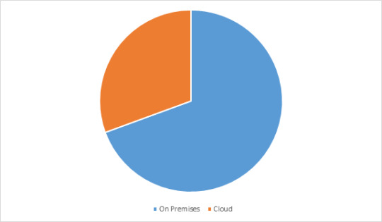
By Deployment Mode : Cloud, On-Premises
By Type : Software (Finite Element Analysis, Computational Fluid Dynamics, Electromagnetic Waves and Others) Services (Design & Consulting, Support & Maintenance, E-Learning & Training, Research & Development)
By Vertical : Automobile, Aerospace & Defense, Electrical & Electronics, Industrial Manufacturing, Healthcare, Education & Research, Others.
By Geography: North America (U.S, Canada, Mexico), Europe (Germany, UK, France, Italy, Spain, Russia, Netherlands and Others), APAC(China, Japan India, SK, Australia, Indonesia and Others), South America(Brazil, Argentina, Chile, Colombia and others), and RoW (Middle East and Africa).
Key Takeaways
Simulation Software market in North America region held significant market share of 34% in the forecast period. Early adoption of advanced technologies in aerospace, defense and others has been increasing the demand for simulation software.
Cloud deployment is growing at a highest CAGR of 20.3% in the forecast period owing to its operational flexibility and real-time deployment ease to companies compared to on-premises deployment.
Automotive sector is expected to witness a highest CAGR of 21.2% the forecast period. Increasing focus on R&D activities and rapid technological changes owing to the changing government norms for vehicle safety are projected to drive the market.
Simulation Software top 10 companies include Altair Engineering, Ansys, Autodesk, Bentley Systems, CPFD Software, Cybernet, Dassault Systems, Design Simulation Technologies, Mathworks, PTC, Siemens PLM Software among others.
Simulation Software Market, By Deployment Model, 2020 (%)
For More Details on This Report - Request for Sample
Simulation Software Market Segment Analysis - By Deployment
Cloud deployment is growing at a highest CAGR of 20.3% in the forecast period owing to its operational flexibility and real-time deployment ease to companies compared to on-premises deployment. It also offers numerous benefits, including reduced operational costs, simple deployment process, and higher scalability in terms of connected resources. Additionally, the cost-effective cloud-based solutions ease installation when compared to the on-premises solutions. The highest level of data security and reliability offered by the cloud deployment are increasing the share of this deployment in the forecast period.
Several companies are providing solutions related to this deployment. For instance SimScale is a full-cloud CAE simulation software that helps to perform CFD, FEA, and thermal simulations for CAD models in the cloud. Similarly, AnyLogi? Cloud is a cloud-based simulation tool that allows users to run simulation models such as Finite Element Analysis and Computational Fluid Dynamics online using just a web browser and share them. Hence these benefits are analysed to drive the market growth in the forecast period 2021-2026.
Simulation Software Market Segment Analysis - By Vertical
Automotive sector is expected to witness a highest CAGR of 21.2% the forecast period. Increasing focus on R&D activities and rapid technological changes owing to the changing government norms for vehicle safety are projected to drive the market. With increasing connectivity and digitalization, OEMs are focusing on improving cybersecurity over connected vehicles & devices, which is expected to drive the automotive simulation market for software such as Finite Element Analysis and Computational Fluid Dynamics. Along with cybersecurity, rapid infrastructure development and advancements in 5G technology companies such as Nvidia, IPG automotive and so on are collaborating with several global companies for advancements in these simulation software.
In 2019, Nvidia had partnered with Toyota for autonomous vehicle simulation platform drive constellation, the cloud-based platform. This platform would enable the self-driving car developers to run tests on virtual, rather than real roads. In 2018, IPG Automotive signed a partnership agreement with Transpolis SAS to develop innovative solutions in the field of large-scale simulation. Hence these factors are anticipated to fuel the growth of the simulation software market in the forecast period 2021-2026.
Simulation Software Market Segment Analysis - By Geography
Simulation Software market in North America region held significant market share of 34% in the forecast period. Early adoption of advanced technologies in aerospace, defense and other has been increasing the demand for simulation software. In addition, the governments in the North American region are constantly focusing on innovation and investment for a greener work environment. The regulations associated with the eco-friendly work environment are becoming stringent in the region and as a result, companies are adopting simulators to test product viability before manufacturing.
In U.S. strict guidelines imposed by the Federal Aviation Administration (FAA) and Federal Aviation Regulations (FARs) regarding use of simulators for training purpose. According to new FAR regulations, Air carriers must compulsorily develop training programs using simulators that meet the upgraded requirements. Stringent regulations as such will drive the usage of simulators thereby driving simulation software in this region. According to U.S. Department of Defense, by 2022, U.S Military had committed to invest more than $11 billion for virtual, augmented and mixed reality training systems and simulator. Hence these factors drive the market growth in the forecast period 2021-2026.
Simulation Software Market Drivers
Growing advancements in simulation software
Simulation software companies are strengthening their position through mergers & acquisitions and continuously investing in research and development (R&D) activities to come up with solutions to cater to the changing requirements of customers. In addition companies such as Siemens, Rockwell, Ansys, and so on are planning to invest in advanced technologies such as artificial intelligence with a target to provide cost competitive Finite Element Analysis and Computational Fluid Dynamics products in the market in the forecast period.
In 2020 Ansys Inc. entered into a definitive agreement to acquire Lumerical Inc., which is a leading developer of photonic design and simulation tools. The acquisition will add a wide range of photonics products to the Ansys Multiphysics portfolio, providing customers with a full set of solutions to solve its next-generation product challenges.
In 2019, Altair Engineering Inc. launched a new manufacturing simulation solution for additive manufacturing, Inspire Print3D. The solution is aimed explicitly at selective laser melting (SLM).
In 2020, Kumux has launched the 2.0 version of its spectral simulation software, which allows the creation of differential lighting, beneficial to people’s health and plant growth.
In 2018, Simufact Engineering, an MSC Software company and expert in manufacturing process simulation, had launched Simufact Additive software solution for the simulation of metal additive manufacturing processes. Hence these advancements are analyzed to drive the market growth in the forecast period 2021-2026.
Growing adoption of simulation software among aerospace & defense
The aerospace & defense industry has been one of the major end users of simulation as they use modelling and simulation for numerous purposes including, training of individual soldiers, conducting joint training operations, formulating operational plans, developing doctrine and tactics, and analyzing alternative force structures, Finite Element Analysis and Computational Fluid Dynamics.
The technology fulfills critical defense needs of command, control, and communications; manpower, personnel, and training; computing and software; electronics; and manufacturing technology. These defense models and simulations vary in a broad range from components of large weapons systems through system-level to simulations of missions and battles, and so forth. Such significant applications are the major factors driving the growth of the global market in these industries.
Simulation Software Market Challenges
Data security is the major challenge for simulation software
One of the major challenges in Simulation Software is data security. Investment in data security to avoid simulation attacks is one of the major challenges faced by the simulation software companies. Simulated attacks might send fake phishing attacks to employees or attempt cyber-attack on a company’s web application firewall. High investment into data security is the major challenge companies which is hampering the growth of the market. However, the introduction of many cybersecurity tools at affordable prices is set to invest in simulation software, thereby driving the market growth.
Simulation Software Market Landscape
Software launches, acquisitions, Partnerships and R&D activities are key strategies adopted by players in the Simulation Software market. In 2020, the market of Simulation Software industry outlook has been fragmented by several companies. Simulation Software top 10 companies include Altair Engineering, Ansys, Autodesk, Bentley Systems, CPFD Software, Cybernet, Dassault Systems, Design Simulation Technologies, Mathworks, PTC, Siemens PLM Software among others.
Acquisitions/Software Launches
In 2020, PTC, Inc. launched a 3D computer-aided design software named as Creo 7.0. This software has the new abilities to put the power of artificial intelligence at the fingertips of the designers, hence making the simulation a unified part of the daily work.
#Simulation Software Market share#Simulation Software Market size#Simulation Software Market forecast
0 notes
Text
EEXI and CII Compliance | Synergy Marine Group
The Energy Efficiency Existing Ship Index (EEXI) is a tool developed by the International Maritime Organization (IMO) to reduce greenhouse gas emissions from ships. A ship's EEXI is a measurement related to its technical design. EEXI approval must be acquired by a ship at least once during its lifetime, at its first periodic survey in 2023. An EEXI value is required for every ship based on its type, capacity, and propulsion principle. With our experienced staff of naval architects, marine engineers, CFD, and FEA experts, we assist with all aspects of vessel-specific emission reduction, including build and class consultation, final survey approval, and guiding owners and operators in selecting energy-efficient devices. We strive to complete projects within budget and on time by providing high-quality work.
0 notes
Text
Exploring Tefugen's FEA Capabilities: Harnessing Advanced Analysis Techniques
FEA is a computer application that uses numerical techniques to assess systems and structures. When subjected to thermal and structural loads, it accurately predicts how components will react. Instead of needing to construct the actual component, using a virtual computer-based model makes it easier to check the design and integrity of a component and pinpoint important areas for development. TEFUGEN offers exceptional FEA analysis and consultancy services to help with simulation-based structural and thermal evaluation of mechanical systems.
In the field of engineering design, Finite Element Analysis (FEA) has developed into a highly promising computer-aided engineering technique for modeling and analyzing structures with complex geometries and changeable material properties. It is commonly used during the design phase of a range of engineering fields, such as automotive, aerospace, power plants, and production engineering, to optimize products that increase performance.
Advantages of FEA:
Minimize the product development cost
Reduce the product lead time into the market
Accurately predict components response to load
Unlimited level of detail in the system
Analyze difficult & dangerous experiments
Easy repeatability of simulation
Linear Analysis:
The branch of FEA known as linear static analysis is most typically used to evaluate the structural and thermal performance of mechanical structures. The applied forces and displacements have a linear connection in linear static analysis. Actually, where stresses remain within the material's linear elastic range, this is relevant to all structural components. In a linear static analysis, the model's stiffness matrix is constant, and the solving time is quicker than in a nonlinear analysis of the identical model. In order to obtain an initial estimate, linear static analysis is usually used before performing a full nonlinear analysis.
Static stress analysis is likely the most common type of structural analysis using the FE technique. Stress, strain, and deformation of a component or assembly can be assessed under various load scenarios to avoid expensive failures during the design stage.
Typically, structural loads consist of one or more of the following:
Outside forces, like the clamping force in subsea connectors.
Surface loads, such as the pressure inside pressure vessels
Body pressures (gravity, acceleration such as centrifugal force in rotating machines)
Dynamic Analysis :
The phrase "dynamic FEA" describes a number of dynamic simulation methods that can be used to analyze even complicated engineering systems. Dynamic analysis is used to design and analyze potential noise and vibration issues as well as to assess the effects of transient loads. As seasoned development engineers, we rarely end our involvement in a dynamic assessment with the analytical output. We frequently collaborate with customers to identify creative solutions that are practical and beneficial from a business standpoint.
Thermal Analysis :
Thermal analysis and FEA can be used to solve heat transmission in or between solids. Convection, conduction, and radiation are a few examples of heat transport mechanisms that can be calculated. However, the analyst directly estimates convection and radiation, not the FEA software. Heat transfer analysis with FEA is normally carried out when the heat convection coefficient can be assumed to be constant along the surface of the part or when the value is precisely known. FEA-based heat transfer analysis can also be used to determine structural stresses brought on by temperature gradients in the component, including thermal expansion.
Buckling Analysis:
By the use of buckling analysis, a structure's stability under compressive loading conditions is evaluated. To verify the stability of the construction, a weight-lifting device will need to be used under compressive loads. The kind of buckling analysis employed in FE analysis is called linear buckling analysis. A static structural study must be followed by a linear buckling analysis. The results of a linear buckling analysis are buckling load factors, which are scales of the loads employed in the static structural analysis. The structure will buckle when the aforementioned level of static loading is attained, according to the simulation's results. There are countless buckling load elements that might affect a building. Every load factor has a distinct instability pattern associated with it, similar to modal analysis. The bulk of us, however, are focused on the load factor that is the lowest.
Fatigue Analysis :
A fatigue analysis is used to determine if a structure would fail after a specific number of repeated loading and unloading, or "load cycles," as opposed to replicating one load cycle as in a static analysis.
0 notes
Last Seen Blogs

yachana
Yachana

sjrresearch
SJR RESEARCH LLC

virtualdonutfestivalnerd
Untitled

p3rs0nne
Chaos

magsmagicalnightmare
Among the fandoms I love