#CableTracing
Text
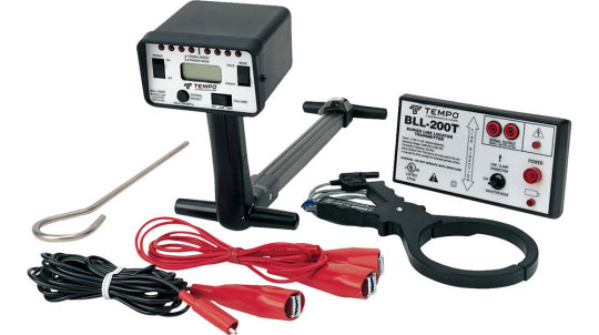
Cable locator: features of cable tracing and identification
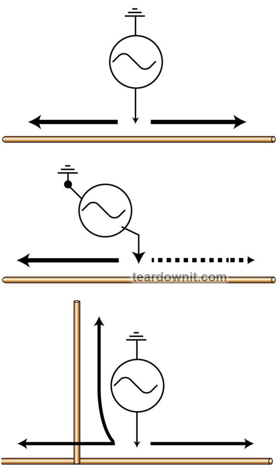
In some cases, a successful result can only be reached with excellent and proper grounding if the probing signal is applied relative to the ground. An incorrectly selected generator grounding location will prevent the probing current from flowing in the search direction if the line to be traced is branched. The transmitter ground point should be changed so the signal is fed in the right direction.
The circuit impedance to which the signal is applied (cable-ground) depends on the ground condition (its type and humidity), the physical parameters of the traced line (size, insulation, etc.), and the characteristics of the grounding. Some generators can match the output impedance to the signal circuit parameters to increase the signal amplitude.
The grounding quality is essential for low frequencies. The better the grounding of the oscillator, the higher the signal amplitude. The ground resistance should be less than 1000 ohms. So a 5-gallon water canister will be helpful - water can always be poured into the grounding point and reduce the grounding resistance. A small metal plate is placed on the surface and watered if you encounter asphalt or concrete pavement. You do not need to use nearby metal structures (water pipes, fences) for grounding because they will emit a signal. You need to remember: if a parallel cable or pipe runs next to the cable to be traced, the reverse current will flow through them, and they will also emit an electromagnetic field therefore. It may take several attempts to experimentally find the best grounding point as a result.
The technique of routing pipelines and cable channels has its own features.
The generator is connected directly to them if they are made of conductive material. The pipeline must be disconnected from the ground at the point where the generator is connected. Otherwise, the signal will take a shortcut. It is worth using inspection pits for direct connection to a metal pipeline or cable channel in the middle of the route. If there are no inspection pits, the pipeline's location must be determined in advance by active or passive search. The connection quality of the generator (low contact transient resistance) to the metal cable channels is estimated by the change in signal level - the signal changes its tone when the load appears in most generators. When you trace cable channels and pipelines, you should always remember that the connection of their segments in some places can be made with non-conductive seals. It is advisable to connect such places galvanically so that you do not have to deal with each piece individually.
Tracing of non-metallic channels without internal conductive elements is done in two ways.
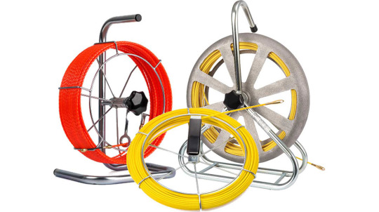
First, a metal CPS (Cable Pulling System) rod can be inserted into the channel, with the generator connected to both the rod and the ground.
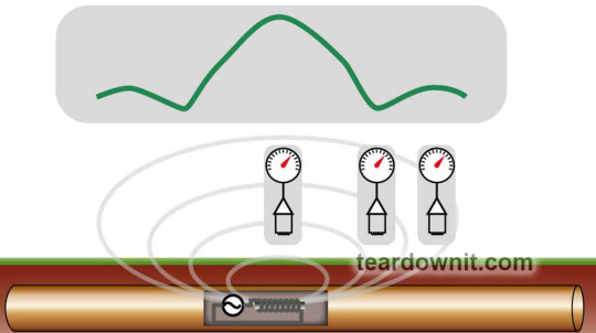
Second, an active probe, a coil-loaded transmitter placed in a tiny capsule, can be inserted into the channel. The probe is attached to the CPS and pushed into the canal, and the active probe coil signal is detected by a receiver equipped with a coil sensor.

The first method is more convenient for tracing, and the second - is for finding specific locations (for example, to determine the location of a clog in the channel).
The signal can be fed to any two unterminated conductors of the cable or between one of the conductors and the building ground bus if you are using the sensor as an antenna.
Since the sensor-antenna "senses" the electric field, the signal is applied in such a way as to ensure its maximum (the circuit at the remote end must be open).
This must be remembered when the signal is applied to a pair of cores that has a defect in the form of a short circuit (reduced insulation) or is loaded (closed) at the other end since the electric field strength (its value is determined by the potential difference) will fall as you approach the point of short circuit.
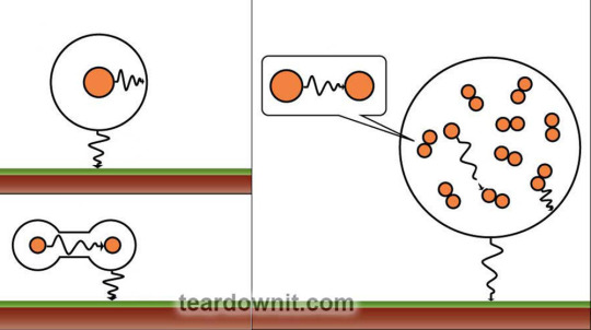
Suppose a signal is applied to one of the twisted pairs of a multi-pair cable. In that case, when tracing (moving the antenna along the twisted pair), it will be maximal when one of the wires is near the probe and minimal at the point where the wires cross. Thus, unlike tracing using a coil probe, the signal level along the traced line will vary periodically. This effect is also possible when the signal is applied between the core of one of the pairs and the ground bus (the core position inside the cable changes all the time).
When identifying the pair to which the signal is applied, the antenna should be brought to one of the conductors, not placed between them - the electric field strength is maximum near the signal-carrying conductors and equal to zero strictly in the middle.

To verify correct identification, short-circuit the pair. The disappearance of the signal will indicate that the pair is correctly identified. Another way to check (by zero signal) follows from the above. Suppose you spread the conductors of the pair in the shape of a V and place the probe antenna in the center. In that case, the correctly identified pair generates a zero signal. It should be particularly noted that a negative result from both tests may indicate not only that the pair is incorrectly identified but also that there is a fault in the correctly identified pair. It can be a breakage or increased resistance of the cores, a symmetry violation (connection errors when two cores from different pairs are used - the so-called "unpairing"), or a reduced insulation resistance of one of the cores.
Because of the many nuances, identifying and tracing a cable with an antenna sensor requires excellent care and attention: carefully observing the antenna's position relative to the wires and not allowing your hand to be near or touch the antenna. Suppose the antenna is mounted on the body of the receiver. In that case, it should be kept away from the wire bundle to reduce the pickup noise on the receiver circuits.
Particular care must be taken when selecting how the signal is fed for tracing. When working with twisted pair cables (especially high-frequency and structured cables), the generator should not be connected to one pair but to the cores of two different pairs or to the core of a pair and the shielding sheath. Remember that the electric field, unlike the magnetic one, is almost entirely blocked by the cable's shielding (foil or braid). For the same reason, it isn't easy to work with wet wires. Therefore, it is better to connect the generator for tracing to one of the cable cores or its shielding and the grounding busbar of the building.
When using a receiver with two switchable sensors (coil and antenna), the signal must always be fed so that the return path does not go through a conductor in the same cable or run close and parallel. Failure to meet this condition (say, the signal is fed to cores in the same cable) will make the sensor-coil operation impossible - the magnetic fields of the conductors will be subtracted as the current flows in them in different directions.
Generally speaking, tracing with an antenna sensor is not very convenient and is suitable only when working in buildings and with suspended cables. This device is convenient for the identification of cable pairs (separation of pairs at the connection of cables or cross) and cable terminations.
2 notes
·
View notes
Link
$1,426.00 $ Chief MWRUB Swing Arm Mount TV Mounts https://nzdepot.co.nz/product/chief-mwrub-swing-arm-mount-tv-mounts/?feed_id=134116&_unique_id=65913c02094b1 Features: -Provides full extension while remaining low profile in the home position -Centris Technolgoy provides fingertip tilt adjustments -CableTrac System provides a fast and effective way to route cables -Swivel up to 90° left or right (depending upon screen size) -Integrated lateral shift 6″ left and right (ships shifted 2.5″ to the left) -Mounting guides provided for a hassle-free installation -Q-Latch Mounting System secures flat panel to mount with a latching flag -Screen can be installed in portrait or landscape orientation (MAC400 accessory can be used to rotate without removing the screen) Specifications: Color Black Lateral Shift 12″ (304.8mm) Maximum […] #
0 notes
Text
Things to consider when Buying a Pipe & Cable Detector
Many of the contractors here in Malaysia does not aware on where to purchase pipe & cable detector. Below are some ideas on what areas that you need to take note before purchasing a pipe & cable detector.
1. Authorized Dealer
This is the most important point to consider before purchasing any equipment. First authorized dealer with guarantee you with original & new equipment. Not any refurbished / used unit. Non authorized unit does not comes with original manufacturer warranty as well as there is not calibration can be done.
As nowadays equipment repair & setting are all over the internet, hence once you connect to the computer for repair/setting/calibration. The system will lock up the equipment.

2. Authorized service center
Authorized service center is another important key point for your consideration, as we know, there is always parts that need to be replace over time. Hence with service center here in Malaysia, it will shorten your repair lead time
3. Calibration
As we all know, all electronic devices required to be calibrated every year. Equipment calibration is definitely in 1 of the ISO audit standards & customer requirement standards
4. On-Training
Cable detector the simplest detection equipment available in the market, however is not straight forward equipment as described by the sales person. You will still need to go through a simple product training on how to operate on the equipment and how to analyse if that is the correctly utility you are detecting.
5. Certificate
Training certificate can be provided by authorized trainer by the principle. This certificate proof your team are fit for the projects. There are some utility owner are also looking into training certificate before the contractor are allow to start the job

After reading all these, are you wondering where you could look for it?
Contact me at 013-3339067 ( Ho) to find out more offers. Feel free to contact or email me at [email protected] if you have any others issue or questions.
There are 3 model of locator, which are CAT4, RD7100, RD8100. Still having dilemma on which model locator to choose? On next I will share with you which locator to select based on your job scope.
#cabletracer#detector#underground#utilitydetector#utilitylocator#cablelocator#cabledetector#pipedetector#undergroundpipe#undergroundcable#RD8100#radiodetection#RD7100#cableavoidance#cable avoidance tool#howtoselect#thingstoconsiderbeforebuying#buycabledetector#malaysia#undergrounddetectiontraining
0 notes
Text
Cable locator: tracing and cable identification
How is the generator connected? How to choose the right type of receiver probe? How to provide a probing current in the line being traced? What affects the range of the locator?
A thorough knowledge of all the techniques of working with the device, of course, does not guarantee error-free results (statistics show that even a very experienced operator during the day can make 10 to 20% of the errors in the total amount of work), but it can reduce the number of miscalculations.
The main tasks that can be solved by the cable locator :
Determination of the cable route (cable bundles) and cable ducts;
Identification of cable lines in a bundle or cable ducts, among others running in parallel;
Identification of cable terminations;
Cable core identification.
Solving each of these problems may require an individual approach - it all depends on the type of line being traced (twisted pair cable, coaxial, power, cable duct, pipeline), its characteristics (cross-section, frequency properties, length), its location (on the surface, in a cavity or in the body of a monolithic building structure, in the ground), as well as the characteristics of the generator and receiver available. Therefore, giving a set of direct and unambiguous instructions is impossible. A system of preferences, however, can be described.
First, you must determine the most effective sensor type for the case in question (coil or capacitive antenna) and the method of signal delivery (direct connection or inductive method).

Direct connection involves physically connecting the transmitter to the line you are looking for, which requires access to either the cable strands or the surface of the conduit (conduit), and provides a rich selection of signal circuitry. In addition, it provides the most powerful signal applied precisely to the desired circuit. Therefore, if direct connection is possible, it should be preferred. The exception to this is when the line is energized. Although the transmitter output is normally protected against AC voltage up to 120 V, it is not advisable to connect it to live cable conductors. In this situation, an inductive coupler or inductive antenna is better suited.
An inductive sensor offers much greater capabilities than a capacitive sensor. However, to use a coil, the signal must be applied to a closed circuit through which sufficient current can flow for the available receiver sensitivity.
If we are talking about two conductors of a cable (a pair of cores or a core and a shield), there are only two cases where such a circuit can be arranged. First, if the remote end of the circuit is accessible and the conductors to which the signal is applied can be shorted. Second, if it is loaded (for example, the conductors are connected to a load or to the input circuits of some equipment). This also applies to pairs of conductors shorted due to reduced insulation resistance.

It is crucial to understand that the range over which the receiver will be able to detect the signal depends to a large extent on the purpose and design of the cable. Since one of the goals of most cable designs (especially high-frequency cables) is to minimize the emission of the transmitted signal, selecting the conductors to which the signal will be fed must be made with great care. Tracing cables in a shield or protective covering (sleeve, wire, or foil braid) is possible because they do not eliminate the magnetic field completely. The signal is much more attenuated in cables armored with a steel tape or wire. It is almost entirely blocked by cable ducts made of steel or aluminum tubes. Therefore, such lines can be traced only by applying a signal to the channels themselves or by accessing the cable in the transition and junction boxes.
The last option to feed a signal into a traced cable by direct connection is to connect the generator to a conductor of the buried cable. In this case, the circuit can be shorted through capacitive leaks to the ground since AC voltage is used as the signal. There is no need to ground the remote end. However, connecting the transmitter to a conductor inside the cable (wire, shield, metal armor, or a central carrier) minimizes the effect of current leakage or signal transfer to nearby objects. For example, coaxial cable with an insulated shield and multipair telephone cable in polyethylene sheath is traced to a greater range than a twisted power cable and multipair telephone cable in the lead. The range is also affected by water in the conduits where the traced cable passes. Remember that a short cable section may not have the capacitive leakage present to provide enough current for the available receiver sensitivity. Then there is only one solution: ground the remote end of the line or switch to a high-frequency signal.
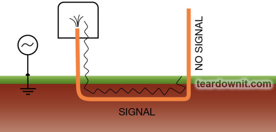
Grounding is also necessary if the cable comes out of the ground (e.g. when arranging an entry into a building). Suppose such a cable section is not grounded at the remote end, starting from where it left the ground. In that case, it will not be possible to trace the line - the current will not flow further because the capacitive connection with the ground will disappear.
When the ground is used as a return conductor, the generator should be placed close to the connection point to the cable. The path of the return current through the ground affects the total field (the magnetic fields of two conductors with different current directions are subtracted), so the grounding point of the generator should not be close to the cable connection point. The metal ground pin used in this case is buried in the ground at a small distance (15-30 ft) to the side and forward in the direction of the cable routing.
0 notes
Last Seen Blogs

ao3feed-aizawashouta
AO3 Feed For Aizawa Shouta


themusingsofaninfp
Simply loud thoughts...

wayvphobic
MILA

alxcsins
empty avenues.