ptiautiste
Things
I'm a intersexual autistic (Asperger flavour, 50+) and diapered 24/7 because of nerve damage. Disabled? Definitively no! A bit different, ok. Bloggin' things i'm interested in and my (often very own) sight of life. Feel free to ask me anything.... NO MINORS! 18/21+ only!
440 posts
Don't wanna be here? Send us removal request.
Last Seen Blogs

thebusinessforumsblog-blog
The Business Forum

miniatureheartpeace-blog
Untitled

justatestttt
Pocket Protectors and Plaid

charwohq
𝔴𝔬𝔫𝔡𝔢𝔯𝔩𝔞𝔫𝔡

prinitha-blog
Le Bliss Spa
Text
6K notes
·
View notes
Text
A better world
I am born intersex, which in my case mean that I was born with both male-typical and female typical sex traits. I was assigned the male sex at birth and because I reserve the right to be in disagreement, with that designation, I am also what is called transgender.
I see myself as a woman, but neither as male nor female.
I have a need to rearrange my sex traits, in a manner where my body will become sexually unambiguous, to the extent that is possible, to alleviate my severe discomfort associated with having male sex traits, as a woman.
I am on early retirement (welfare system, for physically/mentally ill/handicapped people), because of traumatic experiences forced upon me in the Danish healthcare system, on the basis of my status as both intersex and transgender and I have co-founded a human rights organization that aim to spread awareness of the existence of intersex people and what that means, while also working towards recognition of intersex persons human rights, especially on the right to self determination of what happen with our own bodies, that no medically unnecessary procedures are performed against our wishes or without our personal, free and informed consent (Physical integrity) and the right to highest attainable standard of health.
Just as is the case with male and female bodies, there are illnesses and problems related to being male or female, the same is true for different intersex variation, and there are many ways in which someone can be intersex.
As is the case with my variation, issues with expressing ourselves in social situations is often observed, there’s an increased tendency towards anxity, autistic traits are observed in 30-50% of all people with my variation, symptoms of the non-hyperactive form of ADHD, as well as difficulties in regulating our own emotions.
I drew the shortest straw and unfortunately I have traits of all these issues, which I think also had significance in my early retirement. That said, I of course do my very best to find solutions so that I can one day contribute to society, the same as most others, but with a differently wired brain that doesn’t at all match up with how the Danish labour market function, finding a solution has proven very difficult and I have been psychiatrically evaluated to never be able to improve my chances of ever being able to keep a job.
I hope and keep my fingers crossed that in time I can find something that suits my neuro-atypical brain.
One of the ways that helps me regulate my emotions, perform better socially and regulate my negative autistic traits has been to participate in sports. I have a particular interest in martial arts and moving my body has a calming effect on me which also helps me not feel less anxious.
For me, martial arts is a form of very physical therapy, where I can burn a lot of energy, but at the same time, it’s a way for me to achieve the weight loss that is required in most places around the world, to become eligible for gender affirming surgery.
I believe it’s important that we as transgender and intersex persons, share our experiences and lives with society, if we are able to, to participate in fostering a better understanding of who we are and thus create a better society where, we can live our lives as equals, with the same opportunities and rights, as the rest of the population.
I believe that this instead of polarizing, if we have the courage to be vulnerable and have our voices heard, can help create a shared understandings and recognition of the diversity of all people.
It would mean a lot to me, if you would share this post, because the only way I can participate in making a better world, is by reaching a bigger audience.
As intersex and transgender people, we need your help and support to create a better Denmark (and world).
(The photo is from a conference I attended a long time ago, but the message is still relevant)

49 notes
·
View notes

Text
9K notes
·
View notes
Text
AM-Detection -the not easy way
Sometimes quite simple things can be a real nightmare if you take a closer look. One of those is AM detection. Your worst enemies are distortion and fading (the latter results in the first). The AM-Detector is only one little part in a receiver, exactly that kind of part usually no one thinks about. "It works, so what should be wrong with?" -a lot and sometimes there's more wrong than right.
A good part of that distinctive AM-Sound we all know is because of the Detector, even under the best conditions. If you're listen to shortwave or the broadcast band during the night then you also have to cope with Fading. Shouldn't be that problem, the automatic gain control takes care of that, right? Ehmmm... Yes. Sometimes. Why the sound gets so distorted when the signal goes down? Just because it's very often 'Selective Fading' and not just Fading -and your Detector doesn't like it.
Really good AM-Reception has a lot in common with High-End-Audio: if it shall work well EVERYTHING has to be well. So let's just talk a bit about Detectors...
Basically the Detector just splits the Audio Signal from the received and amplified Signal. Sounds easy and in fact it is -up to some degree. If you want more than this things getting complicated -really complicated. In at least 999 out of 1000 AM-Receivers for the Detector a small circuitry called 'Envelope Detector' is used, it's just a small Diode (Tube or Semiconductor), a few Resistors and small Capacitors. So, from the view of the Development Engineer: just put half a dozen cheap Components together and Bob's your Uncle. To tell the Truth: compared to the expense that thingy works surprisingly well. Because of this it's the 'Gold Standart' for this task since at least the mid 30s. But as good as it is, it absolutely has it's Limitations. Up to about 15...30% Distortion at a 100% Modulation Level is one, the inability to detect a signal with different sidebands (>selective Fading!) properly another.
To overcome these Limitations a thing named 'Synchronous Detector' was developed many Decades ago. This kind of Circuit has many advantages over the Envelope Detector, but to make one the complexity and the component count of those is just hilarious compared to the Envelope Detector. If only the result counts and nothing else: that's the way to go. We'll talking later how this exactly works, but before this you have to know that in a receiver with a Synchronous Detector also an Envelope Detector is needed: just for tuning in. So first we'll have a closer look how we can get the most ideal Envelope Detector.
Basically it's quite simple: want to have low overall Distortion? Feed it with at least 'a few' volts RF at it's input for having a high ratio between the input voltage and the 'forward voltage' of the Diode. Want low Distortion at low modulation levels? Use a Diode with low Impedance and a load Resistor with a value as low as possible. Want low Distortion at high modulation levels? Just make the input Impedance of the following Stage as high as possible for having the highest possible Ratio between the Resistance of the Load Resistor and the input Impedance of the following Stage.
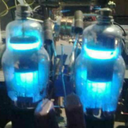
The Receiver i wanted to use (R+S EK07) has an IF output, meant for exactly such things, the IF Level there's about 250mVpp @ 300kHz. So having everything above in mind -and just adding a 700mVpp IF output for the Synchronous Detector and an additional AGC-Circuitry, then we're coming to this:

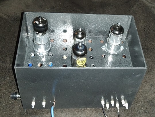
The EK07 is a fully tube equipped receiver, so i also want to use tubes as far as possible and -like in the EK07- in a way which guarantees 10k's of Service hours. If at one point a Semiconductor may perform muuuch better -ok, so then. First of all i want high performance. So what tubes may perform optimal here?
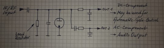
For the first IF-Amp (IF1) not much is needed, the Gain is only about 3, the output voltage low and besides that it has to be an remote-controlled type. Selectivity isn't needed or desired, so no IF-Can, only a Broad-Band setup. Nearly every IF-Tube with a Transconductance of at least about 3000mhos (3mA/V) would do that job. To have better performance i took the EF805s, which is a Special Quality Version of the EF85 -or 6BY7.
Transconductance is about twice what's needed, so we'll have Gain to spare, anyway, it's getting controlled with the AGC so it will work with less current which adds greatly to the service life. So no problems here.
For the second IF-Amp (IF2), things aren't exactly that easy. First: the output for the Synchronous Detector is placed between both Amps and has to deliver a constant voltage, so for the 2nd IF we need an Amplifier with an fixed Gain. A STABLE fixed Gain over long time periods. Further we want to have a relatively high and undistorted output voltage which calls for quite a bit of gain. Wait: there was also that thing with the low-value Load Resistor in the detector itself -so we also need a quite reasonable amount of output power from this stage. In Addition we want to have a stable gain for a time as long as possible. A IF-Tube like the EF805s could also handle this, but then we have to 'beat the crap' out of this thing. Not a good start for a long and stable service life, also not with Special Quality Tubes.
Because of all that my choice was a kinda 'special'-Special-Quality type: the E81L.

The datasheet calls this a 'Long range, Special Quality Tube for the use in Telephone Equipment'. Telephone Equipment? Like an answering machine?? Nope, by far not. Back in these days telephone companies needed to have Amplifiers for pushing the calls through loooong cables for long range service. But: this was all multiplex service, so they pushed dozens and dozens of calls simultaneously through one pair of wires or a Coax. The same way like for cable TV. THIS was these bulbs were meant for. For this task every company employed tens of thousands of such tubes 24/7/365. If a single one failed -most likely somewhere in nowhere of course- they had a problem. So they absolutely had to last.
These little bulbs are designed for about 4.5W plate dissipation at 20mA, the Transconductance is 11000mhos (11mA/V)-so it's about twice an usual IF Tube in every respect. So that's exactly what's needed here: a tube especially designed to last, quite powerful, so we can drive it with comfortable low settings, enhancing service life and stability much further.
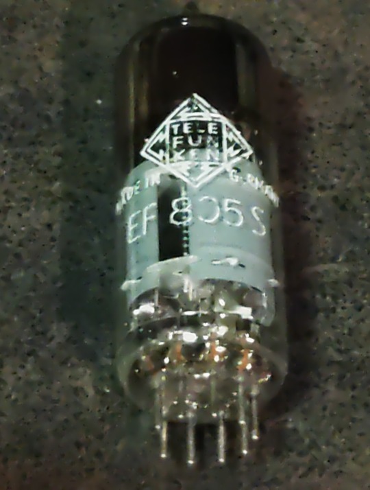
Because we need some amount of power the usual Broad-Band Amplifier arrangement (still: selectivity is not wanted or desired) with just a plate Resistor isn't good here, a suitable inductor works way better here. This has the further advantage that we can build it with a Tab like an Autotransformer -we don't need that much voltage it could deliver with that inductor by far, so this adds further to a good SNR and lower output Impedance. 300kHz trough a transformer? Yep, no problem. Just use the right core. Here it's not a laminated iron core but a ferrite one instead. Cause it's a single-A Amplifier of course we must add an air-gap, preventing saturation.
In a penthode stage the gain depends nearly exclusively on the Transconductance of the tube used, have to much just cut it down. The E81L has a quite high transconductance, about 3 times more than needed -and in the same order than big output tubes like the 6550, EL34 or 6CA7. For cutting that down to the desired level just put a Resistor or Pot in series to the bypass cap of the cathode Resistor. This acts as an series feedback so it also enhances linearity and long time stability greatly. Yap, i thought quite a while about which tube i should use here.
So after all Amplification is done now, we need a Diode for the Envelope Detector. Back in the Octal-Days this was the 6H6 / EB34, later in the Miniature-Days the 6AL5 / EAA91, both with two separate diodes in one bottle (or Can for the 6H6). These were not A DIODE, these were THE DIODE, so there's not much to choose from. Both are kinda close to each other, but are these ideal for what we want? They both can handle a reverse voltage of several hundreds of volts, so waaaay more than we need here. Both having a Plate Resistance of 600-something Ohms per System which is quite low -could be lower, even with both Systems in parallel. Of course these would be work well, no doubt about. But still.... Hey, this should be High-end so we're whining here at a very high level!
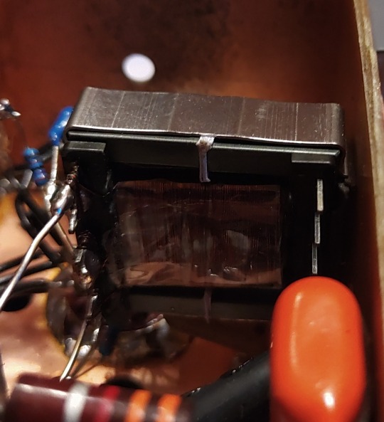
Basically we can use EVERY TUBE as a diode: just take the control grid as Anode, the Cathode as what it is and everything else as Shielding. We don't need hundreds of Volts reverse Voltage, nor high current, so also no big Cathode. We only want to have an internal Resistance as low as possible, so a close spacing between the Grid and the Cathode. This calls for a small Tube with a high Gm (or Transconductance) -like the 6AK5 / EF95. Can it handle the reverse voltage we need? Datasheet says 50V, so at least twice of what's needed. So just take one, put some current trough and take the voltage drop. Result: 210 ohms -way less than that what one of the double-diodes would provide, even with both Systems in parallel. Fits very well!

This is the soviet-military version of the 6AK5W / E95F. Special Quality. See these 'trenches' in the bulb? And the microscopic rivets holding the Plate together? The Soviets literally ruggedized the heck out of this tube! Why? Just because they used it widely in their Fighter Planes, ICBM's, Tanks and so on. Doubts about the soviet built quality? Hey, they wanted to win WWIII with them -so: nope. If you ever saw a ruggedized tube: this it is.
After the Detector itself is done, we come to last part of our little contraption: the buffer Amplifier. At the output of the Detector we have the AF as well with the overlayed AGC-Voltage and we want to have an input Impedance as high as possible for the Buffer Amp. Voltage Gain isn't needed -we have plenty of both from the Detector- so we just can use a Cathode Follower for the buffer. Ideally the Buffer should handle both voltages simultaneously, but then the output will be negative with respect to Ground. How to....? Simple: just put that thing between a positive and a negative supply rail. Then the output can swing freely between every positive or negative Potential as desired. Further: we don't need a Grid Resistor! The Grid just follows any voltage swing of the Detector, this also adds to a high input Impedance.
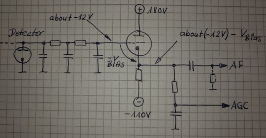
This Circuit will provide us a very high input Impedance, but this is High-End! So: what tube will be the best for? Because of the lack of any Grid Resistor the input Impedance depends now largely on the contact potential of the grid. So we want a tube with low contact potential which calls for a tube with a low Transconductance. Further we want a tube which needs only a low bias voltage for it's Grid, 'cause we'll loose any bias-volt in our AGC-Output voltage. This calls for a tube with an high Gain. Low contact potential and low Transconductance? High Gain?? That's the 12AX7 / ECC83! Ok, it's of course a double Triode, but we still can use the second system for something else -like for the Line-Output Amp. In that Stage there's not much needed so it also will perform well enough there -we're still talking about AM!
So let's put everything neatly together, adding adequate shielding and so on -and we get this:
So now it's time to have a closer look we did everything right. Just put a 300kHz-Carrier in, 100% modulated with a triangle-signal. We should get a perfect Triangle at the AF-Output -if physics are with us. Due to the Triangle Signal any Distortion can easily be spotted on the Scope.
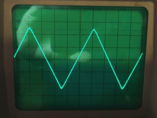
Looks promising! But somehow... Is the beam defocused? Let's take a very close look:

No, it's not. Those are just the very small remnants of the Carrier, so we actually have a look how the Detector works on a nearly 'microscopic' Level. I could take a measurement how much distortion we have left, but the Flanks of the Triangle are perfectly straight, so the Distortion will be really small -like 1% or so worst case. At least for the moment it's not worth the Effort. Compared to the usual 15...30% Distortion at a 100%-Modulation level this works really well, there's no doubt about.
So finally: we wanted to have a Envelope-Detector as good as possible and here we are. Ok, tbh it's better than needed, cause finally the REAL Detector will be a synchronous one. So why i took this that far? Easy: because of mental peace. Now i never have to think about if that part of the whole final thing could work better. As i said before: it's High-End.
Will update you if the next module is ready. But i fear this here was just the more easy part of the whole thing. From now on things may get a bit more tricky...
2 notes
·
View notes
Text
40 plus years of audio wisdom.
Is it egotistical to call my opinions wisdom? Hey this is MY tiny corner of reality so deal with it. I have heard a lot of high end audio equipment, some touted as state of the art. You know what tout means?
First golden rule there is better and good, but there is no BEST. As things ascend the hill of quality the paths lead to things you like. Perfect may not sound the way you want. You may like sugar in your coffee. (Ruins it for me)
Second golden rule is this is supposed to be fun. Do not get angry that people like different things or disagree with you. Appreciate different perspectives.
Every method of sound reproduction has distortion. Every method of measuring distortion has flaws or limitations.
Equipment reviewers are imperfect and human and are motivated by their situation. They almost always give positive comments, they have to. Read between the lines and make your own judgements.
When considering a purchase think critically.
Sometimes you may just want a taste of something different. That is perfectly fine.
Good equipment has a definite voice. Specific brands usually have specific voices that reflect the preferences of the designers. I conclude that this voice is a particular family of distortions that the device has. If there was no distortion it all would sound the same.
Both Tubes and Transistors can be used in high end gear. Neither is inherently better. They each have weaknesses. They are different.
Both pure analog and digital methods and media can be very good. One is NOT inherently better than the other. I have both pure analog and pure digital recordings of impeccable quality. I also have combination of those technologies that are excellent too.
It is great to have high quality recordings of good music. It is fine to have less than great recordings of great performances too. Music is performing art after all.
Psychology and preferences will drive purchases. Nobody is immune. Sales people need to sell. Snake oil products are common. A community of people that believe something reinforce that belief amongst themselves, even if it is false.
I have found that over four decades the absolute quality of audio systems has not improved that much. The golden ear experts described a lot of gear as perfect and realistic and many positive adjectives back 50 years ago. I have assembled systems with older equipment and it is pretty good. Preferences for particular things change.
Try to explore and have fun.
4 notes
·
View notes
Text
One of the rare optical phenomena in nature is rainbow clouds
7 notes
·
View notes
Text
A combination of barrier mesh animation and anamorphic projection on elegant porcelain.
55K notes
·
View notes
Text
9K notes
·
View notes

Text
Finally...
I was looking for a really good shortwave receiver for at least a decade -an old tube equipped one of course. The problem getting one nowadays is that they were only produced in small numbers half a century (or more) ago, since then most are scrapped, botched, altered or corroded cause of bad storage -or all together. So if you have the chance getting one today you most likely will buy a 'construction site', needing hundreds of working hours for restoring it in a good working condition.
But after a looong search finally i had real luck. A big wooden crate was delivered on a pallet.

In this crate was one of the -for my opinion- ugliest shortwave receivers ever built, but at the same time also one of the best ones: a Rohde + Schwarz EK07.
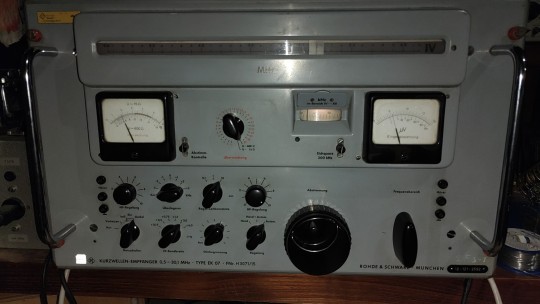
Built in 1958 this one was a storage unit from the German Army. Well stored, regularly maintained and serviced, not altered, not botched, never used. So it is in nearly mint condition. It wasn't cheap but getting my hands on this was just sheer luck. Without doing anything: it's in perfect working order. No potentiometer, no switch crackles, every tube checks new -of course you can check all the tubes in the radio itself without removing them.
The manufacturer is more known for it's precision Lab-Equipment and less for it's shortwave receivers. This is also because their receivers weren't consumer or amateur gear, this was pro gear by any means. They were used in applications like coast guards or military surveillance and such. Always things where equipment costs doesn't matter -only the outcome. So back in 1958 when this unit was manufactured you could buy at least two brand new cars for the same amount of money. In exchange for this you got a masterpiece of german engineering and craftsmanship -and also an electro-mechanical nightmare if anything fails and you're not absolutely familiar with it's guts.
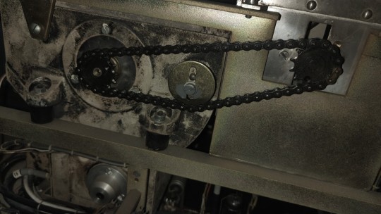
Fancy? No, there's absolutely nothing fancy on these. These are absolute workhorses, designed for doing an important job 24/7/365 for decades. Just take a look to that bandswich gear in the photo above. How often you have to switch over the bands until this would be worn out? Millions and Millions of times... And nope: this dark residues at that drum on the left and box below isn't mold or such. These are completely silver plated so it's just the darkened silver.
As you may see, most of the structural parts are made of die-cast and aluminum, so from the materials used it's relatively light weight. But all that built-in sturdiness and shielding adds up to staggering 147lbs/67kg. It's only a receiver, not a transmitter or a power amplifier.
Tubes... and more tubes
If you're not familiar with tube radios: your average AM (and shortwave) Radio from the 50's or 60's used 4 tubes (without the rectifier if this was a tube). Your trusty Hammarlund or Yaesu shortwave receiver from that time would have somewhat from 8 to 12 tubes -and these were quite good and sensitive receivers! This Rohde + Schwarz counts 28 tubes.

Some tubes here, some there, all fully shielded. But why the hell that much? The answer is quite simple: stability. On every count. Constant and stable gain over all bands and for a looong service time, stunningly stable VFO frequencies and all that stuff. No, they used no consumer tubes like in your TV or such. All of them are out of the 'commercial'-tube-series with a guaranteed service life of at least 10000 hours like in every aircraft of that time or such. Failing was not an option, this HAD to work.
Speaking about stability and accuracy:
this of course isn't digital stuff -it's purely analog. In the pictures below you can see the dials. Just add both frequencies and you know where you are -here on 29.630MHz or 29630kHz.
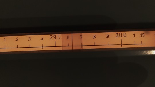

As you see: your readout is easily accurate down to less than 500Hz. So you can read at least 500Hz out of 29630000Hz. With other words the accuracy of your readout is 0.001687% in this case. Your average modern digital multimeter would be proud if it came only near to this 65 year old contraption.
Of course that large dial in the picture on the left isn't the only one. There are 12 of 'em, mounted on a drum and rotating according to the selected band. Giving you a simple S-Meter like in other shortwave receiver was of course also not possible.

Instead they provided you with a Voltmeter which displays directly the input voltage at the antenna input -and the threshold voltage for the 'Squelch' (if you have set that) which isn't a normal squelch. If activated it doesn't cut your Audio, it reduces the Gain instead with a settable time constant, so it acts more like a active noise cancelling between any signal -also between any dash and dot if you're receiving CW (Morse Code). Besides that you can choose your IF-Passband between 150Hz and 12kHz, have a absolutely stable BFO, a good Envelope Detector for AM-Reception and a perfect Audio Stage - that's all.
Speaking of the Audio Stage: 2W undistorted output power from a single end class-A is more than you need with a good speaker. McIntosh ® would call that circuit 'Unity Coupled', further a E88CC for the Audio-Preamp. We're talking about an Shortwave Radio, not an 'High-End' Audio Amplifier. Wanna take recordings of what you hear? No problem: here's your Line-Output, symmetric, 600 ohms, transformer coupled and with +10dBm (if you want) and in accordance to all Studio-Standarts. Sound quality for AM Broadcasts? With a passband switchable up to max. 12kHz for the IF better than the majority of stations can provide.
Precise?
So far so good, but what's about the heart of every shortwave receiver: the Oscillator or VFO? How stable and precisely does it beat after 65 years?
In your trusty -and quite good- Hammarlund or Yaesu amateur Radio from these days the VFO usually is equipped with two tubes: the Oscillator itself and the buffer amplifier -both sometimes also united in one bulb. If i hadn't lost track here they used 12 -and tons of other stuff. So that frickin VFO has a component count which is easily about the order of a complete shortwave receiver.
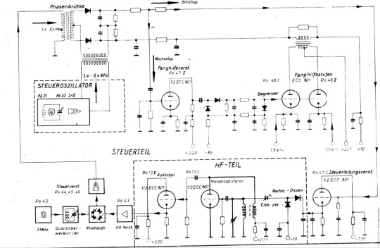
What the hell is all that stuff about -and wtf they had for breakfast back then? The answer is again simple: precision and stability.
As i said: this thing is 65 years old and i touched nothing. Of course I checked how much it's 'off' in terms of the frequency. After warming up for 20 Minutes i checked it every 1000kHz from the bottom to the top of its range. It was a bit different between all points, at some less than 50Hz and about 1kHz worst case.
My Lab-Equipment is quite good and precise, but for these low errors the tolerances of the measuring equipment has absolutely taken into account. So i made a separate measurement only for 10MHz -with the aid of a frequency standard sourced from an atomic clock. So this was 'the real thing'. After warming up for an hour i measured for 15 Minutes. The deviaton was between -717 to -722Hz. Including the error of the dial. This means frickin' 71.7...72.2ppm. PPM -parts per million! 65 years after manufacturing.... Just absolutely stunning -and with what freaking kind of equipment they had calibrated this back then??? Just have in mind: this is pure analog goodness, not a modern PLL. How the f***k they got there? Here's the clear link between a manufacturer of high-grade Lab Equipment and a shortwave receiver. I'm just stunned over the knowledge of the engineers who designed that circuit back then and the precision this was built.
All without doing anything and all it's original capacitors. Yap, i could realign that but tbh it's just wayyy to less been worth the effort. So it will stay as it is.
Nope,
you're not provided with that fancy stuff your new digital or SDR may have on board. There's no notch filter, no panoramic display -not even SSB! Why the hell they just 'forgot' all these things? The answer is easy: it's modular. The EK07 is just the 'mainframe', everything else you wanted to have can be added as external components you had to buy separately -also for tons of money of course.
Wanting SSB? Just add this:

35kg/77lbs and 18 Tubes more -to mention it's also a synchronous detector for AM is not worth the effort. Panoramic display, digital frequency counter, Teletype Adaptor, a remote control for controlling that beast over a telephone line? FM? Diversity reception?? No problem, you had just buy it. Everything of course with the same standards for precision and build quality.
The outcome...
Yea, i spent a good amount of money getting this -but in my opinion it was worth every dime. I wanted a good tube receiver and i got a really good one. Compared to upper class modern Radios it's still a very good radio. So the only thing I have to add is an external SSB/AM-Synchronous Detector. The originals are nearly impossible to get today, so i decided to build one. It's on the way and i will give you the results later. So stay tuned...
2 notes
·
View notes