#shortwave radio
Text
Helms, Harry L. How To Tune The Secret Shortwave Spectrum ( 1981, Tab Books) : Free Download, Borrow, and Streaming : Internet Archive
29 notes
·
View notes
Text
u dont like shortwave radio? bla bla bla?
#only real ones will understand#radio#shortwave#shortwave radio#numbers stations#AM radio#shortwave broadcasting
14 notes
·
View notes
Text
Imagine picking up Honey and Sis on THIS shortwave set, as if having an 8-track player as well wasn't good enow:

#hanna barbera#photo headcannon#kitschy#kitsch#transistor radio#shortwave radio#honey and sis#hannabarberaforever
2 notes
·
View notes
Text
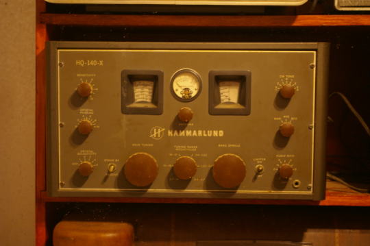
My Hammarlund HQ-140-X. This is the first Hammarlund I bought many years ago.
2 notes
·
View notes
Text
AM-Detection -the not easy way
Sometimes quite simple things can be a real nightmare if you take a closer look. One of those is AM detection. Your worst enemies are distortion and fading (the latter results in the first). The AM-Detector is only one little part in a receiver, exactly that kind of part usually no one thinks about. "It works, so what should be wrong with?" -a lot and sometimes there's more wrong than right.
A good part of that distinctive AM-Sound we all know is because of the Detector, even under the best conditions. If you're listen to shortwave or the broadcast band during the night then you also have to cope with Fading. Shouldn't be that problem, the automatic gain control takes care of that, right? Ehmmm... Yes. Sometimes. Why the sound gets so distorted when the signal goes down? Just because it's very often 'Selective Fading' and not just Fading -and your Detector doesn't like it.
Really good AM-Reception has a lot in common with High-End-Audio: if it shall work well EVERYTHING has to be well. So let's just talk a bit about Detectors...
Basically the Detector just splits the Audio Signal from the received and amplified Signal. Sounds easy and in fact it is -up to some degree. If you want more than this things getting complicated -really complicated. In at least 999 out of 1000 AM-Receivers for the Detector a small circuitry called 'Envelope Detector' is used, it's just a small Diode (Tube or Semiconductor), a few Resistors and small Capacitors. So, from the view of the Development Engineer: just put half a dozen cheap Components together and Bob's your Uncle. To tell the Truth: compared to the expense that thingy works surprisingly well. Because of this it's the 'Gold Standart' for this task since at least the mid 30s. But as good as it is, it absolutely has it's Limitations. Up to about 15...30% Distortion at a 100% Modulation Level is one, the inability to detect a signal with different sidebands (>selective Fading!) properly another.
To overcome these Limitations a thing named 'Synchronous Detector' was developed many Decades ago. This kind of Circuit has many advantages over the Envelope Detector, but to make one the complexity and the component count of those is just hilarious compared to the Envelope Detector. If only the result counts and nothing else: that's the way to go. We'll talking later how this exactly works, but before this you have to know that in a receiver with a Synchronous Detector also an Envelope Detector is needed: just for tuning in. So first we'll have a closer look how we can get the most ideal Envelope Detector.
Basically it's quite simple: want to have low overall Distortion? Feed it with at least 'a few' volts RF at it's input for having a high ratio between the input voltage and the 'forward voltage' of the Diode. Want low Distortion at low modulation levels? Use a Diode with low Impedance and a load Resistor with a value as low as possible. Want low Distortion at high modulation levels? Just make the input Impedance of the following Stage as high as possible for having the highest possible Ratio between the Resistance of the Load Resistor and the input Impedance of the following Stage.
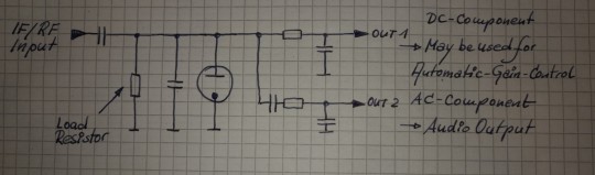
The Receiver i wanted to use (R+S EK07) has an IF output, meant for exactly such things, the IF Level there's about 250mVpp @ 300kHz. So having everything above in mind -and just adding a 700mVpp IF output for the Synchronous Detector and an additional AGC-Circuitry, then we're coming to this:

The EK07 is a fully tube equipped receiver, so i also want to use tubes as far as possible and -like in the EK07- in a way which guarantees 10k's of Service hours. If at one point a Semiconductor may perform muuuch better -ok, so then. First of all i want high performance. So what tubes may perform optimal here?
For the first IF-Amp (IF1) not much is needed, the Gain is only about 3, the output voltage low and besides that it has to be an remote-controlled type. Selectivity isn't needed or desired, so no IF-Can, only a Broad-Band setup. Nearly every IF-Tube with a Transconductance of at least about 3000mhos (3mA/V) would do that job. To have better performance i took the EF805s, which is a Special Quality Version of the EF85 -or 6BY7.
Transconductance is about twice what's needed, so we'll have Gain to spare, anyway, it's getting controlled with the AGC so it will work with less current which adds greatly to the service life. So no problems here.
For the second IF-Amp (IF2), things aren't exactly that easy. First: the output for the Synchronous Detector is placed between both Amps and has to deliver a constant voltage, so for the 2nd IF we need an Amplifier with an fixed Gain. A STABLE fixed Gain over long time periods. Further we want to have a relatively high and undistorted output voltage which calls for quite a bit of gain. Wait: there was also that thing with the low-value Load Resistor in the detector itself -so we also need a quite reasonable amount of output power from this stage. In Addition we want to have a stable gain for a time as long as possible. A IF-Tube like the EF805s could also handle this, but then we have to 'beat the crap' out of this thing. Not a good start for a long and stable service life, also not with Special Quality Tubes.
Because of all that my choice was a kinda 'special'-Special-Quality type: the E81L.

The datasheet calls this a 'Long range, Special Quality Tube for the use in Telephone Equipment'. Telephone Equipment? Like an answering machine?? Nope, by far not. Back in these days telephone companies needed to have Amplifiers for pushing the calls through loooong cables for long range service. But: this was all multiplex service, so they pushed dozens and dozens of calls simultaneously through one pair of wires or a Coax. The same way like for cable TV. THIS was these bulbs were meant for. For this task every company employed tens of thousands of such tubes 24/7/365. If a single one failed -most likely somewhere in nowhere of course- they had a problem. So they absolutely had to last.
These little bulbs are designed for about 4.5W plate dissipation at 20mA, the Transconductance is 11000mhos (11mA/V)-so it's about twice an usual IF Tube in every respect. So that's exactly what's needed here: a tube especially designed to last, quite powerful, so we can drive it with comfortable low settings, enhancing service life and stability much further.
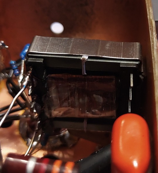
Because we need some amount of power the usual Broad-Band Amplifier arrangement (still: selectivity is not wanted or desired) with just a plate Resistor isn't good here, a suitable inductor works way better here. This has the further advantage that we can build it with a Tab like an Autotransformer -we don't need that much voltage it could deliver with that inductor by far, so this adds further to a good SNR and lower output Impedance. 300kHz trough a transformer? Yep, no problem. Just use the right core. Here it's not a laminated iron core but a ferrite one instead. Cause it's a single-A Amplifier of course we must add an air-gap, preventing saturation.
In a penthode stage the gain depends nearly exclusively on the Transconductance of the tube used, have to much just cut it down. The E81L has a quite high transconductance, about 3 times more than needed -and in the same order than big output tubes like the 6550, EL34 or 6CA7. For cutting that down to the desired level just put a Resistor or Pot in series to the bypass cap of the cathode Resistor. This acts as an series feedback so it also enhances linearity and long time stability greatly. Yap, i thought quite a while about which tube i should use here.
So after all Amplification is done now, we need a Diode for the Envelope Detector. Back in the Octal-Days this was the 6H6 / EB34, later in the Miniature-Days the 6AL5 / EAA91, both with two separate diodes in one bottle (or Can for the 6H6). These were not A DIODE, these were THE DIODE, so there's not much to choose from. Both are kinda close to each other, but are these ideal for what we want? They both can handle a reverse voltage of several hundreds of volts, so waaaay more than we need here. Both having a Plate Resistance of 600-something Ohms per System which is quite low -could be lower, even with both Systems in parallel. Of course these would be work well, no doubt about. But still.... Hey, this should be High-end so we're whining here at a very high level!
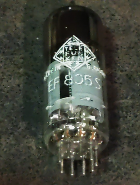
Basically we can use EVERY TUBE as a diode: just take the control grid as Anode, the Cathode as what it is and everything else as Shielding. We don't need hundreds of Volts reverse Voltage, nor high current, so also no big Cathode. We only want to have an internal Resistance as low as possible, so a close spacing between the Grid and the Cathode. This calls for a small Tube with a high Gm (or Transconductance) -like the 6AK5 / EF95. Can it handle the reverse voltage we need? Datasheet says 50V, so at least twice of what's needed. So just take one, put some current trough and take the voltage drop. Result: 210 ohms -way less than that what one of the double-diodes would provide, even with both Systems in parallel. Fits very well!

This is the soviet-military version of the 6AK5W / E95F. Special Quality. See these 'trenches' in the bulb? And the microscopic rivets holding the Plate together? The Soviets literally ruggedized the heck out of this tube! Why? Just because they used it widely in their Fighter Planes, ICBM's, Tanks and so on. Doubts about the soviet built quality? Hey, they wanted to win WWIII with them -so: nope. If you ever saw a ruggedized tube: this it is.
After the Detector itself is done, we come to last part of our little contraption: the buffer Amplifier. At the output of the Detector we have the AF as well with the overlayed AGC-Voltage and we want to have an input Impedance as high as possible for the Buffer Amp. Voltage Gain isn't needed -we have plenty of both from the Detector- so we just can use a Cathode Follower for the buffer. Ideally the Buffer should handle both voltages simultaneously, but then the output will be negative with respect to Ground. How to....? Simple: just put that thing between a positive and a negative supply rail. Then the output can swing freely between every positive or negative Potential as desired. Further: we don't need a Grid Resistor! The Grid just follows any voltage swing of the Detector, this also adds to a high input Impedance.
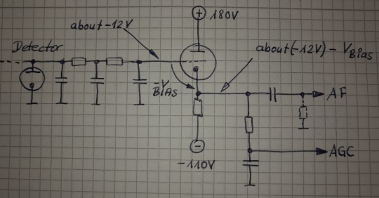
This Circuit will provide us a very high input Impedance, but this is High-End! So: what tube will be the best for? Because of the lack of any Grid Resistor the input Impedance depends now largely on the contact potential of the grid. So we want a tube with low contact potential which calls for a tube with a low Transconductance. Further we want a tube which needs only a low bias voltage for it's Grid, 'cause we'll loose any bias-volt in our AGC-Output voltage. This calls for a tube with an high Gain. Low contact potential and low Transconductance? High Gain?? That's the 12AX7 / ECC83! Ok, it's of course a double Triode, but we still can use the second system for something else -like for the Line-Output Amp. In that Stage there's not much needed so it also will perform well enough there -we're still talking about AM!
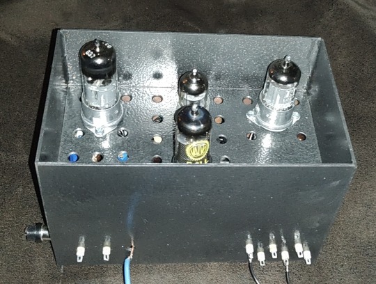
So let's put everything neatly together, adding adequate shielding and so on -and we get this:
So now it's time to have a closer look we did everything right. Just put a 300kHz-Carrier in, 100% modulated with a triangle-signal. We should get a perfect Triangle at the AF-Output -if physics are with us. Due to the Triangle Signal any Distortion can easily be spotted on the Scope.
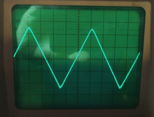
Looks promising! But somehow... Is the beam defocused? Let's take a very close look:

No, it's not. Those are just the very small remnants of the Carrier, so we actually have a look how the Detector works on a nearly 'microscopic' Level. I could take a measurement how much distortion we have left, but the Flanks of the Triangle are perfectly straight, so the Distortion will be really small -like 1% or so worst case. At least for the moment it's not worth the Effort. Compared to the usual 15...30% Distortion at a 100%-Modulation level this works really well, there's no doubt about.
So finally: we wanted to have a Envelope-Detector as good as possible and here we are. Ok, tbh it's better than needed, cause finally the REAL Detector will be a synchronous one. So why i took this that far? Easy: because of mental peace. Now i never have to think about if that part of the whole final thing could work better. As i said before: it's High-End.
Will update you if the next module is ready. But i fear this here was just the more easy part of the whole thing. From now on things may get a bit more tricky...
2 notes
·
View notes
Text
I recorded about an hour and a half of stuff, here's an 8 minute sampler of what I recorded.
Mostly random conversations, but also some weird electromagnetic frequencies, and a few distorted radio stations.
I think my favorite is the Canadian broadcast giving the universal time. The chimes you hear is literally the seconds counting. I recorded this from a Georgian run station.
You can tune into any of these stations yourself here.
4 notes
·
View notes
Text
youtube
7 notes
·
View notes
Text
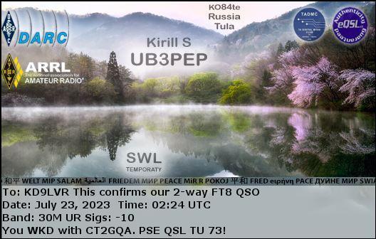
I got an eqsl card from a Russian shortwave radio listener. I always enjoy getting reception reports from swl's.
3 notes
·
View notes
Text
youtube
New harsh noise track...
6 notes
·
View notes
Text
youtube
DJ Stockhausen: Randomly selecting radio stations with control voltage.
7 notes
·
View notes
Video
youtube
LECTURE 21: CARRYING ON: Here is something quite remarkable. In this rare shortwave radio recording from 1971, British DJ and comedian Kenny Everett interviews John Lennon about Lennon’s incredible solo album, JOHN LENNON/PLASTIC ONO BAND (released in December 1970), which contains some of his most mind-blowing music of all time, and is regarded by many critics as the greatest Beatles solo album of all time. Two other Plastic Ono Band singles, “Cold Turkey” and “Instant Karma!,” cemented Lennon’s status as an acclaimed solo musician who could easily hold his own outside of The Beatles. This interview offers a unique glimpse into Lennon’s personal life shortly after the breakup of The Beatles. Well worth a listen.
#John Lennon#Plastic Ono Band#interviews#Kenny Everett#The Beatles#Shortwave radio#Cold Turkey#Instant Karma!#1970
3 notes
·
View notes
Text
Listen to my weird album if you want. It’s about radio waves. Religion? Ephemera. Who knows? it’s unnerving noise nonsense ambience
#music#electronic music#experimental music#ambient#ambient music#experimental#electronic#dark ambient#dark ambient music#shortwave radio#wideband radio#sampling#weird#creativity#weird art#noise#noise music#isolationist music#Spotify
2 notes
·
View notes
Text

Meanwhile, who recalls the HBTV music-video segments during The Funtastic World of Hanna-Barbera Sunday mornings?
(In much the same spirit, I've been known to imagine giving Radio Disney some competition with a shortwave station I'd call "Radio Hanna-Barbera," featuring an eclectic music selection. That, and picturing Honey and Sis, formerly of The Hanna-Barbera Happy Hour, having a pop-up shortwave worldcasting station worldcasting when the shortwave listening confraternity least expects it, operating from a rebuilt GMC motorhome.)
#hanna barbera#photo headcannon#HBTV#the funtastic world of hanna barbera#shortwave radio#shortwave worldcasting#honey and sis#hannabarberaforever
6 notes
·
View notes
Text

my other two Hammarlunds, besides the HQ-180 and the HQ-129-X
2 notes
·
View notes
Text
youtube
Good signals, for a change, listening for doomsday planes and ground stations on 11175 - HFGCS frequencies.
6 notes
·
View notes
Text

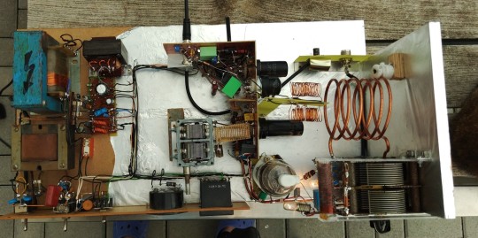
Short Wave Transmitter -old style. Ok, the carrier comes from a PLL-Synthesizer to match modern stability standards. The whole thing works amazingly well...
4 notes
·
View notes
Last Seen Blogs

inkedhungarian-blog
Inked & Hungarian

nonot65-blog
Untitled

wendellmf-blog
MERcÚRIO

wheatkingstrash-blog
Howling the Night Away

nanobomb
reagan YIPPEEE