
alex-mo-tech
Makings of a Mad Scientist
Hello, hello, fellow nerds and welcome to Alex Mo Tech! I post a bunch of my projects and documentation here, even if months after completing them.
Be sure to check my blog below which I will be updating way more frequently and I hope you enjoy my...
23 posts
Don't wanna be here? Send us removal request.
Last Seen Blogs

yourheadisacannon
i write stuff sometimes, it's mostly crack.

amandapearls
If I Could Cuddle My Dogs All Day I Would

hojlundaise
zzz

peachesofteal
Maiden Mother Crone

ricciardonorrisleclercgasly
F1 Fanfictions
Text
UltiCon Part 6: Buttons
This’ll be a short one since, there are soooo many blinky/gpio tutorials out there and I’m sure someone else does it way better than me. The next most important part is the buttons. As long as we have the analog sticks, the screen and keyboard, and the buttons, we have a controller!
Since I haven’t written the main program yet, I’m trying out pigpio, one of tooons of gpio libraries for the Pi, just to check out the differences to wiringpi (spoiler: from the GPIO perspective, I didn’t find them super different...I’ll admit it is kind of nice not having to do all this abstraction ourselves. If you do want to level up your direct register access and embedded skillz and you’ve never done it, give it a shot! If you’re an aspiring firmware engineer, you WILL do it on the job).
The only interesting part here is that the Pi allows pullups/pulldowns on all GPIOs and interrupts on all of them as well (which is not true with all microcontrollers). That gives us a huge amount of freedom when we need to pick what needs to go to which pin.
With our little dev board, we’ve got a great starting point since all of the GPIOs are put into a spot and we just need to reference the GPIO ports we want to read from (promise, schematic is coming, just haven’t set it in stone since I need to get all these tests out of the way).
First, let’s start by downloading pigpio. Follow the instructions on this page: http://abyz.me.uk/rpi/pigpio/download.html.
If you check out the repo, under dev/buttons (https://github.com/amckeeota/UltiCon/tree/master/dev/buttons), I have two examples: buttontest.c and buttonIntTest.c. buttontest uses a polling loop and delays to check the button lines and see if anything has been pressed. Then it prints combos on the screen (try any combo and it should show which buttons you pressed). buttonIntTest registers a single function where we handle what to do with button presses and tell it we’re interested in both low to high and high to low transitions.
To build them, just type
make button
for buttontest.c or
make button_int
for buttonInt.c
For programming in C, the API docs are here: http://abyz.me.uk/rpi/pigpio/cif.html
And for python, they’re here: http://abyz.me.uk/rpi/pigpio/python.html
I’m only using C since I want the final project to be coded in C.
I only used a handful of API functions:
gpioInitialise and gpioTerminate to initialize the pigpio library
gpioSetMode to set all of the button GPIO to input
gpioSetPullUpDown to set the internal pull up resistor to the button
gpioRead for buttontest.c to read the GPIO in the polling loop
gpioSetISRFunc for buttonIntTest.c to set an interrupt in response to a button press or release
Feel free to check through my code for how to use them.
The only thing we seem to be missing is debouncing. I’m a big proponent of debouncing living in hardware just because it’s a little sloppy to deal with in software. This will guide some revision to my original board.
Oof sorry to be so barren from images this post but it turns out GPIO is pretty straightforward if you’re not doing it form scratch. Any questions though and I’ll gladly answer!
0 notes
Text
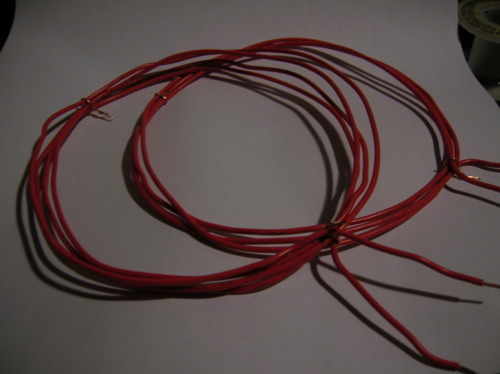
UltiCon Part 5: Burnt Boards, PerfBoards

Fig. 1 - My mess o’perf
Oof. I was working in my quarantine space at night which doesn’t have a desk lamp yet...I think I tied one of the power pins from the chatpad to the raspberry pi I2C driver which ended up in some reverse polarity madness so my chatpad is poofed until another one comes through ebay.
So I’ve been obsessing over a little perfboard based prototype this last week. It’s hard to find time after work or on weekends because of the wee one so this will have to be this week’s post. I’m attaching all my peripherals and making sockets for them which should pretty much ensure that I don’t mess up again as long as I point it the right way (which I’ll pay way more attention to now...).
Some key features:
I flipped some of the male pin headers for SPI so the 3.5″ LCD hookups can still sit on top of the Pi.
I used (made) 90 degree female header rows for the analog sticks, D-pad, and A, B, X, Y boards. I’ll plug them in just to test them, but when it comes to enclosure time, I’ll use ribbons to connect them so I can mount them to the case wherever I wan to.
Because of the direct-plugin test strategy with analog sticks and the buttons are really close together so the LCD and chatpad cover part of the buttons and sticks. I’ll fix that in the final PCB but ya gotta start somewhere!
My pinouts completely changed because everything needs different places to go. It kind of also inspired me to get rid of the I2C chip power pins and replace them with control buttons for the wifi/bluetooth and to add an IR blaster I can use for IR control, thereby further solidifying this as the Ultimate Controller of all time!!!
Alrighty, anyway, just some pictures for now. I’ll schematicize it and everything in a later post.
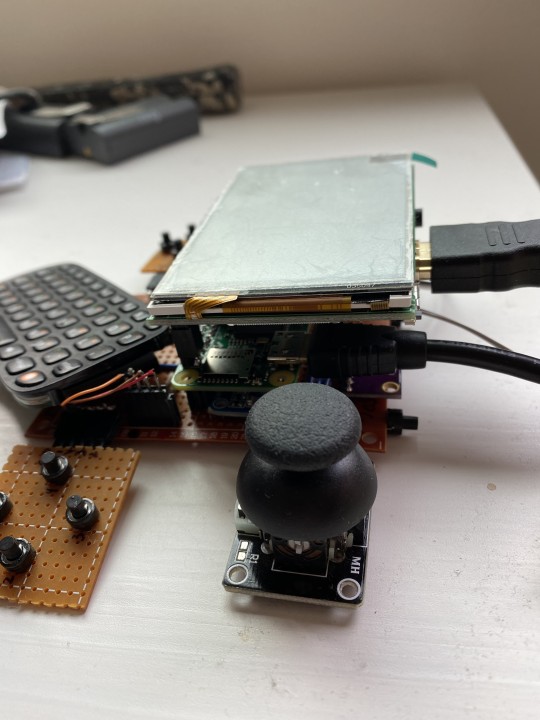
Fig. 2 - You can kinda see the sandwich of ADC, IMU, Raspi, and LCD if you squint
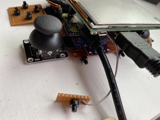
Fig. 3 - Hrm...why did I even take this pic? To show that it has shoulder buttons?
1 note
·
View note
Text
UltiCon Part 4: The Analog Sticks

Fig. 1 - Ignore the breadboard, it’s coming in the next post. Also, the ADC is under the Pi.
Holy crap this project is totally moving along! Next up are the analog sticks. At their core, analog joysticks are just two potentiometers attached to springs. They are (hopefully) centered at 0.5*Vcc, though there is likely some error in there. Moving them to one extreme, down for example, will give you 0v and moving to the other gives you Vcc. One pot takes care of up and down and another pot takes care of left and right. That means we have 2*2 analog inputs that we need to digitize which is perfect since the ADS1115 has 4 single-ended ADC channels!
Here’s some material on single-ended vs differential: http://ww1.microchip.com/downloads/en/DeviceDoc/Differential-and-Single-Ended-ADC-WhitePaper-DS00003197A.pdf
Some also have a “select” button for when you push in the analog stick. The one I got also has a pad to add a pullup resistor if you like.
The Raspberry Pi has internal pullups/pulldowns on all of its GPIO which is a super bonus since that means we can save a ton of space by not adding rows and rows of resistors for each button (the final design plan has 12).
So really, it just comes down to interfacing with the ADS1115!
There are probably a lot of libraries out there. As you hopefully know by now, this is a “how you do it” blog where we don’t spare you the gory details of writing the code so here’s how we do it from scratch.
The Hardware Hookup
First let’s investigate how the hardware gets hooked up.
I2C lines always need to be pulled up with a resistor. It’s because they use what’s called an “open collector” design. At the SDA and SCL lines, on each side, there are transistors with the SDA & SCL on the collector, the emitter to ground, and the base controlled by the I2C module. That means when the base-emitter is activated, it pulls the SDA and SCL low strongly. But when the transistor is turned off, the collector just floats so it needs to be pulled up.
So the circuit becomes pretty dead simple. Here’s a Fritzing breadboard for it.
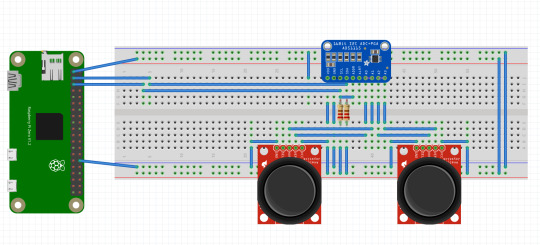
Fig. 2 - ADS1115 breadboard layout. Lots of iterations before I got it looking so clean ^^;
The Software
For the test software, we need to know the registers we’re dealing with. For that, we turn to the datasheet here:
https://www.ti.com/lit/gpn/ads1115
Some things to pull out from the datasheet:

Fig. 3 - Table showing why we chose this chip
We chose the ADS1115 because it gave us 4 single-ended channels and an I2C interface. You can see there are other models with other combos of channels, sample rates, and resolutions and we can choose SPI versions as well so these can be factors to make a good part decision.
The doc outlines how we can set the device’s address using the ADDR pin:
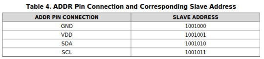
Fig. 4 - Table showing how to change the slave address
On the perfboard, I ended up having to tie to SCL which is shown in the breadboard diagram too, yielding the address 1001011 or 0x4B.
It also shows how to perform writes and reads over I2C (pg. 24) and the registers (starting on pg. 27).
Essentially, to write, we send in this order:
Device’s I2C address (0x4B)
We send the address pointer value
0x00 for the conversion result register
0x01 for the ADC configuration register
0x02 for the Low threshold (which triggers the RDY pin when crossed)
0x03 for the High threshold (which triggers the RDY pin when crossed)
Send the data to write (for config register, Low thresh, and high thresh)
Writing to the conversion register tells it to start the conversion, then we have to wait until the conversion finishes. You can configure the registers to trigger an interrupt on the ALERT line which we may do later. For now, let’s just check that the basics are working.
We can wait a requisite amount of time depending on our sampling rate. For the demo, I’m sampling at 860 samples/sec just because that’s plenty fast for the analog sticks for now. The delay has to be at least 1.2ms to which I added just 20us as a buffer.
After that, we can issue a read command to the conversion register.
Install wiringpi
sudo apt install wiringpi
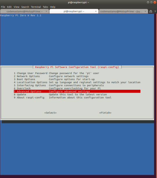
Enable I2C
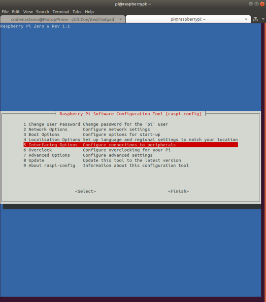
sudo raspi-config
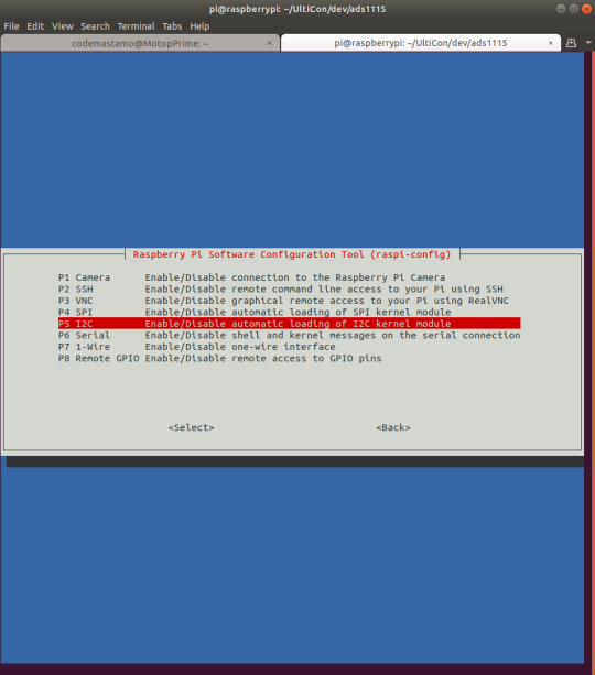
Interfacing options
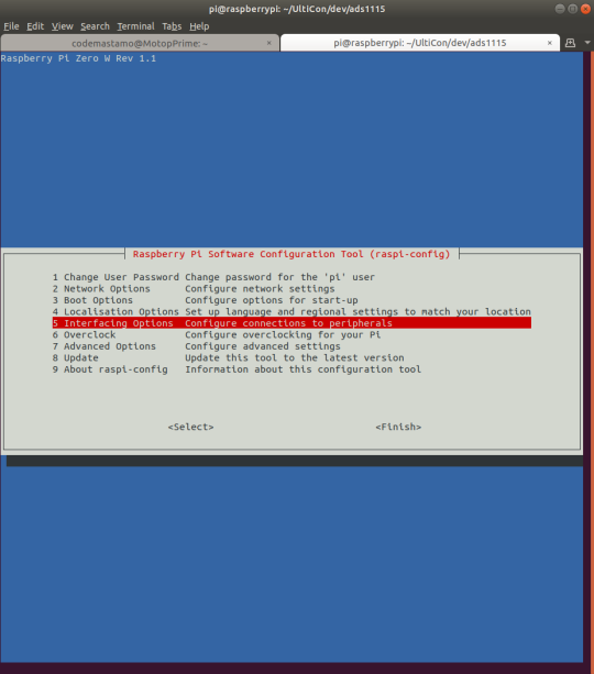
I2C
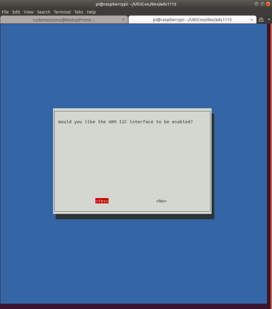
Would you like the ARM I2C interface to be enabled - yes
ARM I2C interface is enabled - Ok
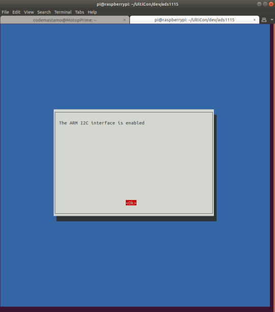
It won’t prompt you to reboot but I had to reboot.
You can download my demo ADC program on github
https://github.com/amckeeota/UltiCon/tree/master/dev/ads1115
To compile it just use gcc like so:
gcc adcTest.c -o adcTest -lwiringPi
and that will give you access to wiringPi’s libraries.
So this is our starter program. Down the line, we’ll turn it into a useful API, do some threading (allowing multiple programs to run at once), and tie it into the main program but, for now, it looks like we can get analog input from the ADS1115!
1 note
·
View note
Text
Chatpad + Raspberry Pi
Alrighty, we’re in the last steps of making the pi accessible in miniature. A lot of the setup is the same as in the last post.
1. Enable serial from raspi-config and disable console
In order to access the serial port we need (/dev/ttyS0), we need to disable the terminal on serial and enable the hardware serial. Here’s how we do it:
Go to raspi-config:
sudo raspi-config
Go to Interfacing Options
Go to Serial
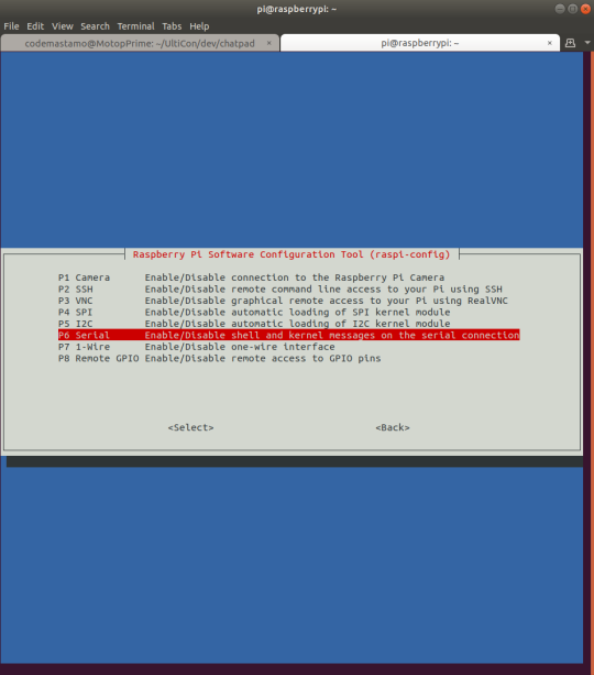
When you are asked if you would like a login shell over serial, enter “No”

When it asks if you would like the serial port hardware to be enabled, answer “yes”
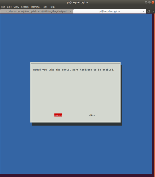
Finally, it will ask if you want to reboot. Go forth and reboot!
2. Install python3 and pip3
sudo apt install python3
sudo apt install python3-pip
3. Install serial
sudo pip3 install serial
4. Install python-uinput as before
git clone git clone https://github.com/tuomasjjrasanen/python-uinput.git
cd python-uinput
python3 setup.py build
sudo python3 setup.py install
sudo modprobe uinput
That last step is just so that we can test the script.
Try running the script from my repo as a sanity. it should work https://github.com/amckeeota/UltiCon/blob/master/dev/chatpad/chatpad_pi.py
5. Make the uinput module load on boot by editing /etc/modules
sudo nano /etc/modules
add the line
uinput
to the end of the file and save and close with ctrl+x, then press y for yes to save it.
6. Make the python script load on boot by adding to /etc/rc.local
Open /etc/rc.local
sudo nano /etc/rc.local
Add the line
sudo python3 /home/pi/path/to/chatpad/folder/chatpad_pi.py &
to the file just before the line “exit 0″
7. Reboot and try it out!
sudo reboot
And you should be chatpaddin’ away!
0 notes
Text
XBOX Chatpad Redux
Alright, so let’s revisit the chatpad.

Fig. 1 - The final test setup
Warning, we’re reverse engineering the protocol. That means it takes loops, it gets confusing, but I try to lay it all out on the table how I reverse engineered the protocol.
Last we left it, I didn’t have a complete writeup on how it works. That is likely because I never got it running.
Back when Ben Heck used one and inspired all the makers out there to follow suit, he reprogrammed the onboard PIC. I think Microsoft has since done some rework on the board that makes it hard to reprogram.
I think that’s a step too many in the process anyway. I’m okay following Microsoft’s crazy protocol.Here is the
So here’s what I’ve learned from the internet:
Here is a pretty great page from Jason Birch on how to interface with the chatpad. I think a lot of this work will just be a repeat of what he’s done years ago, but making and reversing protocols is a muscle and you should make sure to work it out!
The key for us are the connector and the protocol as he’s described it. I know he wrote a driver but I’d rather just write my own. I’ll post the code on github.
First, note it’s just a UART port. Back in this blog when I was bitbanging all of these protocols, it was a bit mysterious, but this is a really widely accepted protocol; it can go wicked fast (Some TI MCUs go up to 3Mbps) down to wicked slow (9.6kbps). You typically don’t need to know how it works except that it does. That’s the neat thing about engineering is that a lot of these technologies are so ubiquitous that to use a serial channel doesn’t take much work, but to tune it and use the right protocol for the job takes some deeper knowledge.
Anyway, on the inside of one of these things, there is a plug-in connector with 7 lines. the bottom 3 are for audio passthrough and the top 4 are power (3v3), RX, TX, and ground from top to bottom.

Fig. 2 - The chatpad connector. I cut off the bottom 3 since I don’t need them and kept just the serial wires. From top to bottom it’s 3v3 in, RX, TX, Ground.
There are only two important commands we need to send to the chatpad: an init command and a keepalive command.
The keepalive is sent every 1 sec. per Jason’s post and those two packets look like this:
(Init frame)
0x87, 0x02, 0x8C, 0x1F, 0xCC
(keepalive frame)
0x87, 0x02, 0x8C, 0x1B, 0xD0
This is a fantastic place to start.
We can maybe glean that a header includes 0x87, 0x02, 0x8C and the remaining bytes 0x1F 0xCC and 0x1B 0xD0 are maybe explaining what kind of command we’re sending.
Anyway, from there, I didn’t find a lot of readily available information
Let’s decode what the chatpad is sending back by recognizing some patterns:
The Reverse Engineer
For the reverse engineer, we need:
A laptop or computer
A 3.3v USB-Serial converter
A logic analyzer
A couple resistors for safety
For the USB-Serial converter I use this one
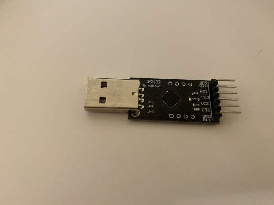
On the back you can use a solder bridge to set it to 5v or 3.3v which I soldered to 3.3V.
Here’s the hardware setup:

We start with a python script that just does the keep alive stuff and prints out the rest. I was really naive and just read 10 bytes at a time looking for patterns but ultimately put the Saleae to the TX from the chatpad to see what came out. Here is the simple python script:
https://github.com/amckeeota/UltiCon/blob/master/dev/chatpad/chatpad.py
To use it, you must first make sure you first have python3 and then pip install serial
sudo apt install python3
sudo apt install python3-pip
pip3 install serial
sudo pip3 install serial
And what follows is the analysis from the Saleae.
It looks like we get a periodic string 8 bytes wide. A random sampling is
0xA5, 0x45, 0xF0, 0x03, 0x00, 0x06, 0x06, 0x17
The next one is the same and so is the previous. They come at about every 77.7ms
After some time (~3 seconds into my capture), I ended up with the same byte pattern but with 0x16 at the end.
0xA5, 0x45, 0xF0, 0x03, 0x00, 0x06, 0x06, 0x16
This may indicate the end of some initialization sequence and that we can now use it.
I typed the letter ‘A’ in and got the following changes:
0xB4, 0xC5, 0x00, 0x00, 0x37, 0x00, 0x00, 0x50
which I get 4 times at intervals of 38.4ms, then it takes another 77.7ms between the last frame and the next retry set which are
0xB4, 0xC5, 0x00, 0x00, 0x00, 0x00, 0x00, 0x87
which it does another 4 times if I don’t do anything.
After a keepalive, it changes to
0xA5, 0x45, 0xF0, 0x04, 0x80, 0x06, 0x06, 0x96
at an interval of 77.7ms
It takes 4.1975 s or 54 of that message before it changes back to the 0x16 message followed by the 0x17 message.
My theory so far into analysis is that we’re getting feedback every 77.7ms on the state of the chatpad and this just says that the LED is still turned on.
After reinitializing the periodic signal was coming back as
0xA5, 0x45, 0xf0, 0x04, 0x00, 0x07, 0x07, 0x14
So can’t seem to find the method in the madness.
Anyway, I pushed ‘B’ to get back
0xB4, 0xC5, 0x00, 0x00, 0x42, 0x00, 0x00, 0x45
which I get 4 times regardless of a keepalive, then the same
0xB4, 0xC5, 0x00, 0x00, 0x00, 0x00, 0x00, 0x87
4 times again at intervals of 38.4ms, thenback to 77.7ms for a signal
0xA5, 0x45, 0xf0, 0x04, 0x80, 0x07, 0x07, 0x94
After 4.1975ms, back to
0xA5, 0x45, 0xf0, 0x04, 0x00, 0x07, 0x07, 0x14.
Test 3: A and B after another initialization:
Okay, one more initialization and I have a periodic of
0xA5, 0x45, 0xf0, 0x04, 0x00, 0x08, 0x08, 0x12
So the last three bytes are changing.
On hitting ‘A’, I get my 4 repeats of:
0xB4, 0xC5, 0x00, 0x00, 0x37, 0x00, 0x00, 0x50
Followed by
0xB4, 0xC5, 0x00, 0x00, 0x00, 0x00, 0x00, 0x87
Next up,
0xA5, 0x45, 0xF0, 0x04, 0x80, 0x08, 0x08, 0x92
Then, hitting ‘B’, I can see 4 repeats of:
0xB4, 0XC5, 0X00, 0X00, 0X42, 0x00, 0x00, 0x45
Then our (kind of) expected
0xA5, 0x45, 0xF0, 0x04, 0x80, 0x08, 0x08, 0x92
Alright, we’re getting a bit of a pattern!
Pattern 1: The Periodic
It looks like the base periodic takes some form
0xA5, 0x45, 0xF0, 0x04, 0x00 0xAA, 0xBB, 0xCC
Our long string of periodics after pushing the button look like the same string with the bit 0x80 set on the 5th and last byte
0xA5, 0x45, 0xF0, 0x04, 0x80 0xAA, 0xBB, (0xCC | 0x80)
I guess we don’t really care about those, but neat to know.
Pattern 2: The buttons
Next up are the buttons. First I tried pressing ‘A’, then ‘B’, then the sequence
A down, B down, A release, B release.
I found that a press or release event triggers the 0xB4 0xC5 strings (x4) every time. A looks like this:
0xB4, 0xC5, 0x00, 0x00, 0x37, 0x00, 0x00, 0x50
Then pressing B, I get 4 of these:
0xB4, 0xC5, 0x00, 0x00, 0x37, 0x42, 0x00, 0x0E
Releasing A, I get:
0xB4, 0XC5, 0X00, 0X00, 0X42, 0x00, 0x00, 0x45
and finally, releasing B:
0xB4, 0XC5, 0X00, 0X00, 0X00 0x00, 0x00, 0x87
So it looks like the 5th and 6th byte indicate the first and second button pushed and, when released, they shift so that the second button goes to the first position.
Hitting shift, square and circle respectively gives me:
0xB4, 0XC5, 0X00, 0X01, 0X00 0x00, 0x00, 0x86
0xB4, 0XC5, 0X00, 0X02, 0X00 0x00, 0x00, 0x85
0xB4, 0XC5, 0X00, 0X04, 0X00 0x00, 0x00, 0x83
And combining any of them seems to add them all together. For example, shift + square yields:
0xB4, 0XC5, 0X00, 0X03, 0X00 0x00, 0x00, 0x84
which leads to our next set of revelations: byte 4 is the “modifier” byte and the last byte seems to be a checksum. Going back to the A+B example, when both were held down, we got 0x0E which is 0x87 - 0x37 - 0x42 so it looks like the checksum is:
Last byte = 0x87 - modifier - button1 - button2
Knowing this, I went through the whole keypad, mapped the characters, went a little overboard, and ended up with script #2:
https://github.com/amckeeota/UltiCon/blob/master/dev/chatpad/chatpad_decode.py
What whaaaaat?! So as long as we’re running the program, we can print a letter per line on the screen. This is way further than we got the first goaround.
So the problem is this: we have the UART going through our interpretter program and then spitting out on the screen. We want to use that as an internal Linux keyboard though...how do we go about doing that part?
I almost thought I had to write my own Linux device driver which I’ve, admittedly, never done. But then I found out about uinput whose job is to take what a program spits out and write it directly to the Linux input subsystem! It’s like it was made for this kind of job!
Talk to the OS with Uinput:
I’ll finish this up in python. On my github I’ll post the C version as well since that’s my target but Python sure is nice for building things quickly!
On Python all we have to do is install python-uinput by following the instructions on the python-uinput repository at https://github.com/tuomasjjrasanen/python-uinput
For posterity, I’ll add the instructions here:
Download and unzip the master of the repo or run
git clone git clone https://github.com/tuomasjjrasanen/python-uinput.git
Go into the directory
cd python-uinput
Build using the instruction:
python3 setup.py build
Install using the instruction:
sudo python3 setup.py install
Next, you’ll want to load the uinput driver (the driver level that lets you send events)
sudo modprobe uinput
and that’s it!
Try the keyboard example to make sure that, while you’re running it, you see “hello” printed to the screen.
What we’re doing now is sending events to the Linux input subsystem so that our program looks like it’s some piece of hardware sending keyboard presses to the Kernel. It basically means we get to skip writing a device driver for our keyboard. We’ll do it eventually but today is not that day.
So now our system looks like this:
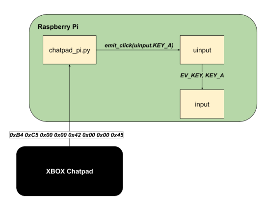
The chatpad is sending serial data and that serial link is being maintained by our application. When the app gets a character input, we look for the right event to send to uinput, and send it. That tells Linux that a keypress has occurred and we can unchain our keypad from the boundaries of the program and out into the entirety of Linux.
You can find all of the keys we can use in the input-event-codes.h header under usr/src/linux-headers-x.x.x-xx/include/uapi/linux/input-event-codes.h
Really, take a gander though. It has the regular keys, but it also has the interesting keys like brightness, bluetooth on/off, play/pause, email, and lots of other interesting keys and combos.
For this project, I had planned on using special switches for wifi on/off and bluetooth on/off to save power but now I can do it straight with the uinput driver which, if you ask me, is a sweet deal.
So the last script ends up looking like this:
https://github.com/amckeeota/UltiCon/blob/master/dev/chatpad/chatpad_decode_uinput.py
Please visit my github, I’ve got the Saleae captures I took to reverse engineer and you can see for yourself how the signals look.
I’m afraid I’ve run out of time but, on the next post, I’ll update with how to integrate everything with your raspberry pi.
I think I just picked the quickest way to decode the input from the chatpad but not the optimal one so I’ll tinker with that.
Til next time!
0 notes
Text
UltiCon Setup Menagerie - Raspberry Pi and the UCTRONICS Screen

I ordered a 64GB SD card to transplant my project (read: collection of crappy PoC programs) so I had to get the RasPi again which is kind of a perfect opportunity to show how to get your Raspberry Pi up and running.
I usually prefer to start in headless mode. If you’re more comfortable with a GUI, it’s totally fine, don’t let anyone bully you into using command line. Just do it because you want to learn it. It comes with the benefit that, if you don’t use X you get some performance gains, though I’m not sure how much (let’s run metrics someday!).
These will be instructions for a Linux computer since that’s my daily driver. If you haven’t tried Ubuntu these days or encountered a million problems in the past, trust me when I tell you it’s very approachable these days and very stable.
Let’s Setup Headless Mode!
Okay so let’s setup headless mode. You can also find these instructions on the Raspberry Pi Foundation website: https://www.raspberrypi.org/documentation/configuration/wireless/headless.md
1. Download a Lite version of Raspberry Pi OS from The Foundation https://www.raspberrypi.org/downloads/raspberry-pi-os/

2. Flash it to your SD card
Find your SD card first in /dev. For this, I like to be doubly sure by either opening GParted (a GUI program that allows you to format disks in certain ways but also shows the size of disks) or running fdisk -l to find the disk that is the right size. For me, that is located at /dev/mmcblk0. Replace that as needed in the command below
dd bs=4M if=2020-02-13-raspbian-buster-lite.img of=/dev/mmcblk0 conv=fsync
It will be completely quiet until you get a new prompt which means it’s finished.
3. Once you’ve done that, let’s get it ready so that you can access it. The first thing you want to do is make sure you get ssh access.
Mount the partition named “boot” from the SD card and, cd into that directory, and create an empty file called ssh
cd /mnt/boot
sudo touch ssh
4. Next, in the same directory, make a file called wpa_supplicant.conf and put in your wifi credentials and the country code for the country in which you live. This will make it connect to your wifi immediately upon booting. I have a file I always copy that looks like this.
ctrl_interface=DIR=/var/run/wpa_supplicant GROUP=netdev
update_config=1
country=US
network={
ssid="greatestSsidNameEver"
psk="superstrongpassword"
}
But change your country code, ssid, and psk as appropriate.
That’s it for headless mode. Plug it into your pi, let it boot and then you can ssh into it!
First Pi Things to Do
I didn’t really mean for this to turn into a Pi tutorial but here we are.
The first thing you want to do when you get into your pi is to change yuor password using
passwd
Next up, make sure your filesystem is expanded so that you get to use all of that space.
First launch raspi-config
sudo raspi-config
Then hit “Advanced Operations”
Then “Expand Filesystem”
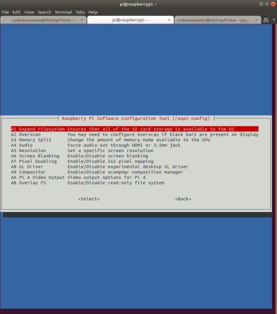
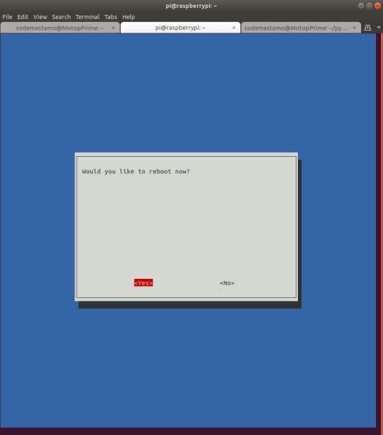
hit Yes, Finish, then let it reboot.
Now, it’s always a good idea to install git but it will also be needed for the UCTRONICS screen. Run
sudo apt install git
Finally, update everything with
sudo apt update
sudo apt upgrade
Getting the UCTRONICS Screen Working
So I don’t put the device on the headers first. I start with just HDMI first and make sure I can flip it and get the scaling right.
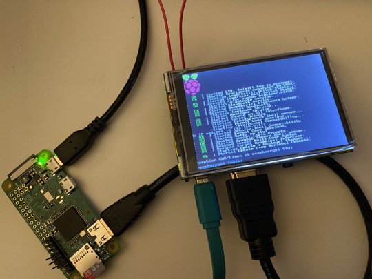
When you first plug it in it looks like this:

What we’re going to do is pull scripts from github and then run them to basically just set the screen settings on boot.
1. Clone the repo
git clone https://github.com/UCTRONICS/UCTRONICS_LCD35_HDMI_RPI.git
It gives you a new folder called UCTRONICS_LCD35_HDMI_RPI which contains a README.md. I shouldn’t have to tell you to read it but, if you don’t, I’ll copy the instructions down here:
Go into the Raspbian directory within that folder
cd UCTRONICS_LCD35_HDMI_RPI/Raspbian/
Make the scripts executable
sudo sed -i -e 's/\r$//' *.sh
chmod +x *.sh
Backup your settings
sudo ./backup.sh
And finally, install the driver.
sudo ./install_uc_touch_180.sh
That will trigger a reboot and, when everything comes back up, it should be at a size that you can read. The problem I found was that whether I ran install_uc_touch_0.sh or install_uc_touch_180.sh, it would be the same direction so I ended up also having to edit /boot/config.txt
sudo nano /boot/config.txt
and then add at the end of the file
display_rotate=2
for 180 degree rotation on every boot.
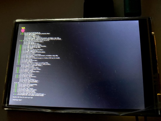
And that’s it! Now it looks like this.

Alright, we’re at a fantastic starting point for the next steps. Tune in next week for more and, for the most up-to-date code, I’m keeping my repo updated with all my tests so feel free to check it https://github.com/amckeeota/UltiCon
Til next time!
0 notes
Text
SpotMicro Controller
Between Amazon Prime and Netflix and Hulu and HBO Max and this new NBC dedicated channel and Qibi, I thought there was just too much media out there to possibly watch...and then quarantine happened...
My tops for quarantine so far have been
Tales from the Loop
Undone
Bojack Horseman
Infinity Train
to name a few.
But from that first series, Tales from the Loop, come these walky bois:

Fig. 1 Still from Tales from the Loop
I instantly fell in love and it sent me on a trip looking for how the heck to make one of them...I mean, how in the world does a bipedal robot do what it does? From what I read, it’s basically an inverted pendulum problem where the legs are just in charge of catching the center of mass as it swings around. It’s really interesting to boil it down that way, especially when you imagine it can sway side to side.
Instead of jumping straight into the toughest goal (as I usually do and then fail miserably with unfinished projects), I decided to start smallish. So say “Hi” to Spark-E (credit to my wife for the name), my quadruped starting point pal!

Fig. 2 - Pic of my Spark-E (minus the bearings for the joints...was too impatient...)
I just opened up my Ender 3 (vanilla) for the quarantine which gave me a chance to find this project. The frame is 3D printed and takes quite a few days even if you’re going nonstop. I’ve done just the base frame because I have some ideas in mind for how I want to run it and there is a community working on AI around it.
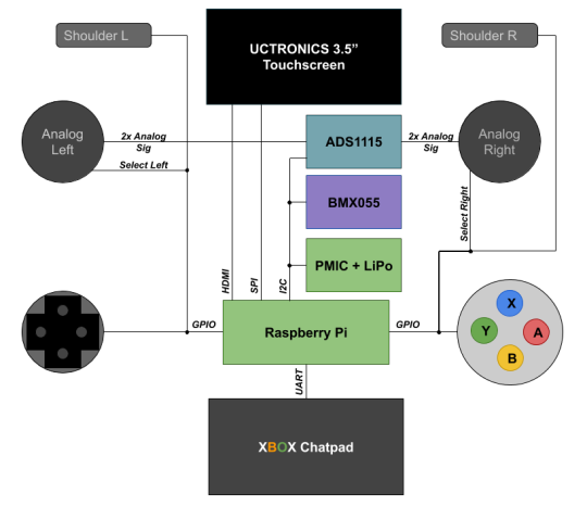
In the meantime, I thought “Hey! I need some kind of a controller. So here is the layout of my dream controller and what I plan to do with it.
At it’s core, the controller will be a battery powered raspberry pi zero w. It will be game controller-ish so you can control the robot like a character.
That means it will have two analog sticks with push-in select buttons on each one. Since Pi’s don’t have ADCs built in, we’ll have to use one on the outside and attach it in. We usually have a choice of SPI or I2C to communicate with these guys, but which one should we use? More on that in a minute.
I want a d-pad for some on-screen menu selection, and some buttons to do neat functions (ugh am i just reinventing an xbox controller?). For that extra controller-like icing on the cake, I’ll stick on some L and R shoulder buttons.
I think it will be really handy to have a screen but I also want text input for the Linux terminal so I’m revisiting the xbox chatpad project from earlier. The chatpad will take up one of my UART lines, and the screen I have (from an earlier project) uses HDMI and is a touchscreen (based on SPI). That means my SPI port is taken up, so our ADC should use I2C.
My ideal controller will also have tilt control which I’ll measure through an IMU. I was already gonna stick one on the SpotMicro so I just bought two.
This is all possible thanks to 40 glorious pins, most of which are usable for signal (the rest are power). Here are how the pins work themselves out for now. If there are changes, I’ll make an updated post:

Fig. 3 - Oof, never again with these trapezoids...Green for serial interfaces, Blue for GPIOs, and Red and Black for power
Everything is 3v3 powered with, of course, similar logic. In my memory, the chatpad was I2C but I was obviously wrong so I’m unfortunately stuck using two valuable pins. :(
So for part selection, here’s what I ended up with:
ADC: 4 single-ended channel ADS1115
IMU: HiLetGo BMX055 9-DOF sensor (I couldn’t discern it from the more expensive Adafruit kind in terms of specs besides that it spits out raw data instead of using an ARM M0 to collect the info into some abstracted numbers)
Analog Sticks: DEVMO 5PC sticks
XBOX Chatpad (the one I have has the Microsoft branded chip. Get from ebay if you’re cheap! I got mine a long time ago and this is apparently the Amazon listing I followed)
Screen: UCTRONICS 3.5″ Touchscreen
I can’t really recommend them or not yet since I haven’t played with them enough yet.
Is it a lot? Yes. Absolutely. Is it even overkill? Are you kidding me? Of course it’s overkill.
On the interfacing side, I really want the controller to be flexible so I’m putting a switch for enabling and disabling bluetooth and wifi. Wifi will let Spark-E join the controller’s network and then we can use some IoT magic to send some commands between them. They’ll be over an encrypted channel but don’t let that throw you for a loop, it’s just the difference between drinking soda through a clear straw vs an opaque one - in the first one, you can see it’s a dark soda and can glean it’s coke, in the second one, you can’t tell, but they’re really similar form factors.
Why Bluetooth? Because I might not just use this with Spark-E. This is gonna be the Big Kahuna of controllers after all! Any new thing I make, I want to use whatever interface makes sense.
Alright, I think I’ve blathered long enough for an intro. Next up are prototyping each of the interfaces. I’m sorry but we’re going to be mixing languages. Sometimes it will be mostly in Python which I’ll throw up on the githubs and then the final program code will be C just because the structure makes sense to me and we can eek out some performance.
Alright! Signing off. More next weekend!
0 notes
Text
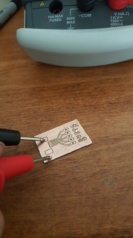
Fun with Eagle
In anticipation of using a new part, I have the pleasure of learning to do everything from PCB layout to programming the thing! One of those things is to experiment with making PCB’s, and with much finer detail than my first etching tutorial (thank god). I’m not going to totally go over the toner transfer method since you can get that ANYWHERE on Google. Even artists use it. This is more another voice in the fray on my experiences and that worked for me and things that didn’t.
Here are the steps we’ll take to make boards:
Make our board design in Eagle.(If there are any parts that we bought/that aren't right in Eagle, we'll make them ourselves with relative ease)
Find a good printer to print them
Do the transfer
Etch the board
Clean it up
Drill the holes
Solder your parts
Pizza!
DESIGN IN EAGLE
First we do our design in Eagle. I followed two tutorials, one from Sparkfun for making parts and one for board layout, whose link I lost but, trust me, it’s quick and easy enough.
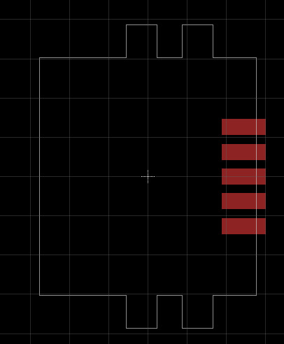
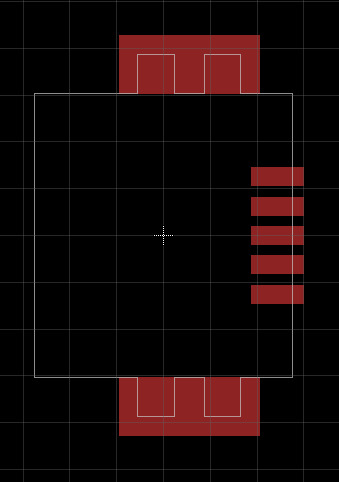
First, I had a mini-USB connector I bought from mouser for cheap so I went to find the part in Eagle. This is the part:

And this is the Eagle footprint:
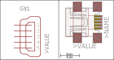
you can see my part only has two little tabs that are close together on each side, but the other one has two pads that are further apart.
So clearly the one in the library is a tad different from ours. To make it better, I made the footprint myself.
MAKE A PART
Here are the steps to make a part;
1. Make the layout (the schematic symbol for the part)
2. Make the footprint (how the part will be soldered to the board)
3. Make the part (link the pins in the layout and the footprint)
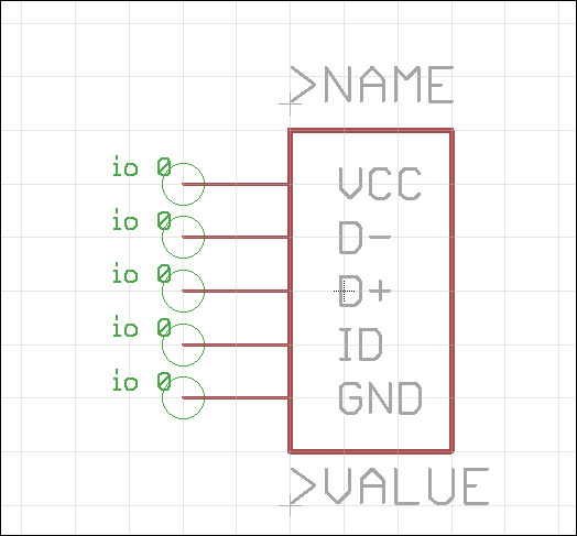
First you make your part layout which is easy enough. Here’s my block with a few pins on it for the USB. I did it this way but you can draw it any way you want. If you wanted a circle to represent your USB, be merry! Just know people will find it annoying if not charming. The whole part of this comes straight from the tutorial.
The most annoying part about making the part was dragging and dropping. For the most part, they tell you not to change the grid size and to only change the Alt size. That makes it so that, as long as you hold down the Alt key, you can move at that tiny of a step size. But imagine you’ve got it down to 1/100 mm and it can get pretty aggravating. Instead, you can use the command prompt at the top.
I found a couple of the commands to be REALLY useful. The anatomy of a command is;
COMMAND (coordX coordY) (coordX coordY)
The three really good ones are
wire t (x0 y0) (x1 y1) - draws wire path between (x0,y0) to (x1,y1) with thickness t
note: if you have the angled mode turned on, it will do a diagonal between the two points, if not it will do an L to form a connection between those points.
move (x0 y0) (x1 y1) - move the object on (x0,y0) to (x1,y1).
Beyond that, another good one is that if you use the > modifier, it will do a group move between relative points. What that means is that, if you do
move (>0 0) (0.4 0.3)
it would move everything in the group by 0.4″ on the x, and 0.3″ on the y, and
move (>1.4 100.05) (1.9 101.05)
would move the group by 0.5″ on the x and 1″ on the y (since it is the difference in coordinates that is important).
Lastly, copy will take an object and copy it to a location of choice:
copy (x0 y0) (x1 y1) - copies an object located at (x0,y0) to location (x1,y1)
For example, if we have an object centered on (1,1) and we want to make a copy centered on (1,2) we can do
copy (1 1) (1 2)
That will super help us to make the footprint.
Here’s a quick pictorial walkthrough:
1. Find the dimensions on a datasheet:http://www.mouser.com/ds/2/185/ed_UX_20140717-515437.pdf

Fig. 1 - Clearly from Hirose Electric Co. LTD, not me.
So we know two things- first, dimensions are in mm, and second, the highest precision we need is just 0.1 mm.
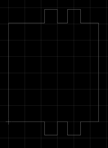
Now let’s draw the footprint. Let’s start with drawing the outline of the physical part.
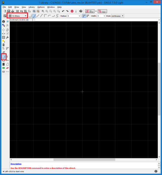
1. Switch the grid to mm and, under alt, change to 0.1 mm.

2. Click on the Wire button and then change the layer to tDocu.
3. Start sketching out the part using the dimensions provided. I wanted to show off so I drew it all in one command. You do the coordinates based on the drawing. Here are the final answers, check against them:
wire 0 (0 0) (0 7.7) (2.8 7.7) (2.8 8.75) (3.8 8.75) (3.8 7.7) (4.6 7.7) (4.6 8.75) (5.6 8.75) (5.6 7.7) (7 7.7) (7 0) (5.6 0) (5.6 -1.05) (4.6 -1.05) (4.6 0) (3.8 0) (3.8 -1.05) (2.8 -1.05) (2.8 0) (0 0)
and you should have something like this:
Now group the whole thing and then type this into the command prompt
move (>0 0) (-3.5 -3.85)
This will make it easier to draw the pads where we want them.
Next we’ll lay down some pads. From the datasheet, it looks like each of the pin-pads should have dimensions 1.4mm x 0.5mm so click “SMD Pad” and then type in its dimensions and put one on the origin.

Next up, take a look at the datasheet. Looks like there are 5 pads, with the centers of each 0.8 mm apart so we’ll do:
copy (0 0) (0 0.8)
copy (0 0) (0 1.6)
copy (0 0) (0 -0.8)
copy (0 0) (0 -1.6)
So now we should have five pads spaced properly but not on the right part of the part.

From the datasheet, it looks like the final place for the center of the pad should be at 0.5 + 5.4 + 0.7 = 6.6mm. They are already at 3.5mm (center) so we just need to shift them to the right by 3.1mm.
Group them, then move them by 3.1 by doing
move (>0 0) (3.1 0)
Lastly, we’ll need the two pads that will physically secure the case.
The next pads are 3.8mm x 1.6mm so click SMD pads and adjust the dimensions like before and stick one on the origin.
Next, we know the center should be 5.6 + 0.5 - 1.9 = 4.2mm from the front of the USB plug. It’s already 3.5 so we’ll say we need to move it 0.7mm horizontally. The vertical is 7.7/2 + 1.6/2 = 4.65 mm. So...
move (0 0) (0.7 4.65)
Then put another pad on the origin and
move (0 0) (0.7 -4.65)
The final result should look like this:
Excellent! Part made!
I just wanted to show how easy it is to get precise positioning using the commands since I think it’s easier to get parts exactly where you want them.
Keep following the tutorial and name your pads. In this case, name according to which outputs they will be.
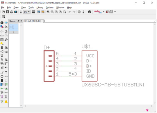
In this case, from top to bottom, the five are VCC, Data-, Data+, ID (insertion detect), and GND.
There is much speculation about the case (whether it should be tied directly to ground, put through a resistor, put through a capacitor, etc etc. For the sake of simplicity, we’re just giving them their own pads.
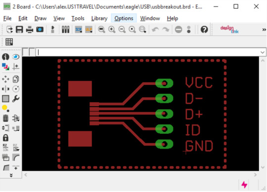
Finish up the rest of the tutorial by linking pads to pins and you will be in good shape with the part. From there, I made a pretty simple PCB that breaks out the part’s pins to a standard male header.
PCB Schematic:
PCB Layout
Next, we have to get this PCB onto a sheet of paper.
THE BEST WAY I’VE FOUND SO FAR IS TO USE A LASER PRINTER ON GLOSSY MAGAZINE.
I thought I could fool the system and use regular paper or a wax printer and there might be something to eitherh of those things, but really, the glossy paper and laser printer yielded GREAT results and isn’t a variable worth tweaking.
Turn off all layers except for top, pads, vias, basically only the things you want to show on your board.
Next, export it by going File -> Export -> Image

A dialogue will pop up. Name a file, make sure it’s in

Export it to somewhere in only Monochrome with the resolution at 600+ I would say.
After you’ve exported, open it with GIMP. GIMP will retain the physical dimensions after you open the image while paint or Inkscape will not without fussing. Also, we’re going to want to invert the colors to etch the right parts.
First, we’ll flip it 180 deg, then invert the colors and fill in any voids you need:


I tried “beating the system” and printing on normal printer paper, but there’s no substitute for the glossy stuff. Pick up magazines from your local store, get housing listings, whatever you can to get some nice thin-ish glossy paper, and use a laser printer to print your design. Since I was experimenting, I printed a few at a time.
Some recommend a hot iron at this point but I found it too annoying for small stuff. If the iron moves the design the slightest bit, it will smudge and the tiny traces and pads will bridge. Besides that, you usually have to tape your design down and I just ended up with mucky smelly molten tape after this.
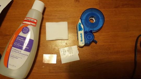
The better way I found was to use those cotton blot pads and good ol’ fashioned nail polish remover. If you soak the paper by blotting it as you lay it lightly onto the copper, then roll it out using a rolling pin or a metal rod, you get a very nice transfer.
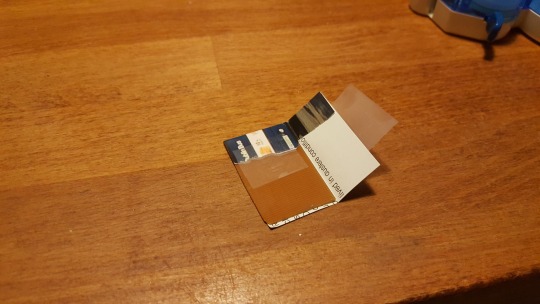
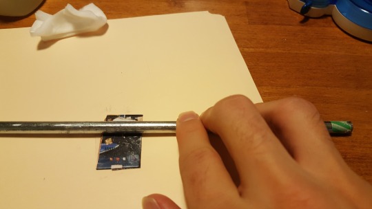
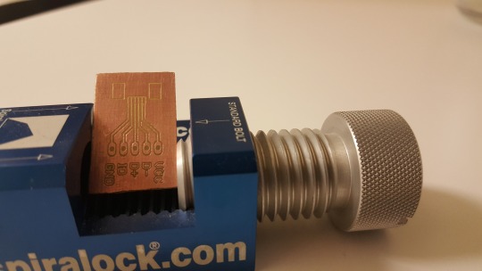
Soak it in water and remove the excess paper by rubbing it gently. I didn’t have to clean anything up from bridges or anything and the whole design transferred except for some fringe parts where I didn’t press hard enough. For that, I used sharpie:
(I promise it was in focus on my tiny cellphone screen!)

I don’t know if you need to but I like to go over it twice to make sure it’s really well masked. Also don’t be afraid to overlap with the transferred toner.
Next, just etch as usual (submerge in a bath of FeCl or, better yet, a more environmentally friendly etchant) and slosh it around a bunch. I don’t think I need to say this but just look at the FeCl...LOOK AT IT. Okay, now I shouldn’t have to tell you you want to wear gloves, use a plastic container to hold it and your board, and to be careful not to slosh it on yourself.
After it comes out you ought to be able to look at it through the light and you should get an overwhelming sense of self-gratification.
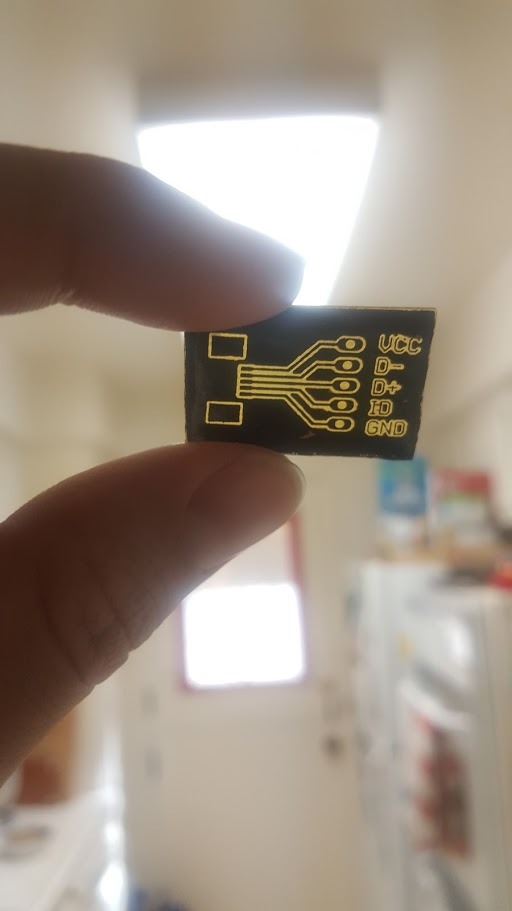
Clean the board up by abrading it with some fine steel wool and it should shiiiiiiiiine.
Test the connectivity and use something pointy to clean out any channels that are bridged.
If all looks good, you’re ready to drill!

Go in slowly because these drillbits are TINY! I used a # to start, and then went up to a # since the headers weren’t that small (measure twice blah blah...).
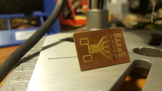
Solder it up and then pizza :)


Fig. I dunno...24? - Valentine’s Pizza
0 notes
Text
T2E Chatpad
am in LOVE with the XBOX Chatpad. I think it’s an awesome interface device. It’s engineered in a very clever way where it enters a low power mode when you’re not using it to save on the ever taxed battery, it’s got a sleek layout, and it’s small enough that you just want to add it to every single project. Besides that, it operates on four wires at 3.3v, and just communicates over UART. The main computer on the board is a PIC so it can even be reprogrammed as you like if you’re into that sort of thing.
My work is heavily based on Cliffle’s blog so, if you like this, be sure to give him kudos.

The Hardware
I’m afraid I didn’t take any pictures of the disassembly of the Chatpad, but it’s really a few screws here and there keeping it together. Once you get into the meat of the thing, you’ve got a very compact, no BS device that looks like this:

Physical dimensions are about 101mm x 43mm. If you desolder the audio port and connector, the madimum height is about 8mm adnd, with the connector, can get down to about 14mm
On board is a PIC chip and a port to the controller connector which, for my own sake, I just chopped off and soldered some headers but there’s a neat hack where, if you have a PIC programmer laying around, you can reflash the firmware as described here: http://forum.arduino.cc/index.php?topic=58463.0 and using these pads.

I haven’t had the pleasure of PIC-ing (but someday!) so I just tried to interpret the protocol preloaded on the board.
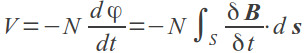
The cable looks like so.
We’re interested in the top four wires - power, UART RX, UART TX, GND (RX and TX are from the perspective of the chatpad). The bottom three wires are just for audio. The UART operates at 19.2 kbps and the whole packages operates at 3.3v.
We will go off of only the following first rule: in order to turn the thing on, we need to send two messages: wakeup and initialize. We're going to do things the hard way because that’s how we learn. Instead of using a single 3.3v Arduino both with UART and serial monitoring, we’re going to use the MSP430G2211 (no UART, no monitoring at 19.2 kbps) and a Saleae logic analyzer. It will help us grow as programmers and fast.
Making a UART Library (in progress)
Making the Chatpad Library (coming soon)
0 notes
Text
Fancy DSP: Intro to the 1D Kalman Filter
The quarterly inspirational speech is a staple to every bachelor’s engineering class and, when carefully executed, it can set the tone for the entire quarter, making it continuously relevant and interesting.
I remember a particular controls professor who asked, poignantly, “how do you come to terms with the fact that everything you’re learning is from a half century ago or further?”
It seemed a validly rhetorical question…until he waited for a response. After 30 awkward seconds, the kid who feels obliged to answer every question answered this one in a terrible unsatisfactory way.
Anyway, the point of this story is not only to explain how awkward life is; it is to explain that, I get it now. The Kalman filter is an incredibly versatile filter invented back in the 60’s but, sometimes, older things are ingenious and worthy of being remembered decades and centuries later.
INTRODUCTION
The Kalman filter is an iterative prediction filter. It uses statistics to generate Normal curves of where a variable of interest should lie at the next sample point, based on data from normally distributed measurement sources.
Yeah, yeah, I know...what?
Basically, I like to see it like this:
Nothing you experience is "real," right? I mean, everything is a measurement of the "real world" with some measure of error. When something is sufficiently close to what we expect or want, then we call it accurate or even "true."
The idea behind the kalman filter is that we have all these expectations of how something will act. By considering all of the variables that go into how it will behave (and leaving the rest up to error), we can do the following:
Predict what the parameters will be the next time we sample
Measure to see what the parameter is
Consider how far off we are from our prediction
Weight the measurement vs our prediction so that we can decide how much to shift our measurement to get the REAL version.
Part of our measurement is what we actually see and part of it is what we expect to see. Let's pretend for a moment we're a dog trying to fetch a ball from our owner. The owner typically does a wind up and then a throw so here are our factors to considerations:
x[n-1] = what the current parameters are (where the ball is, how fast it's moving, if it's accelerating -- we're a pretty smart dog)
x[n] = the parameters we expect to see (where we think the ball will be, what it's velocity might be next, what its acceleration might be in the future, per our current parameters and how we've seen the ball thrown before)
z[n] = what we want to measure (where the ball is!)
Here's our process.
Use v[n-1], a[n-1] and p[n-1] (velocity, acceleration, and position) to determine what we think the new p[n-1] and v[n-1] will be. This is the "modelling" part of the process.
Use the current measurement (which may be very far off from the true value) of p[n] (scaled) plus some combination of the parameters that determine the measurement of interest, z[n], to estimate z[n] (the position).
By finding how far off we are from the prediction, we can come up with a scaling factor called the "Kalman Gain" which determines how much this difference matters
Use our sate prediction (x[n] from the modelling part) plus the error in the measurements weighted by the kalman gain to determine what the new true parameters should be.
And then we repeat. We plug the new parameters that we just calculated from step 4 into our step 1 process, calculate all new errors, and keep estimating and checking our work.
It's a bit of a process and I know we've used a lot of words where we engineers like equations so let's bring it home with some equations, an example and plenty of images.
The Equation
The basic equations looks like this:
K is, again, the Kalman gain calculated each iteration. It depends on what we think the errors will look like in our model (if there are parts we haven't considered and how much they'll effect our prediction) and the errors we expect in our measurement (just how noisy we think our measurement will be).
We constrain so that the noise is only Gaussian and the error we predict will be the variance (or covariance when it comes to the multivariable case). Here's how that happens:
There are great papers on the derivation for this (I'll stick em at the bottom) that involve the maximum likelihood estimate and some curve fitting maximization.
Pretend We Have a Noisy Voltmeter...
This is a pretty common example and I've seen it all over the place when I was doing research on this topic. There's only one measurement that we're curious about (voltage) and it only depends on one parameter.
Say we are measuring a DC voltage of 12V. Since we know the measurement is going to be DC, and we can turn our multimeter knob to DC, we can use the "DC algorithm," which we'll go ahead and develop here.
The parameter is voltage. We ask ourselves, how does the next voltage depend on the current voltage? Well we know they ought to be equal. So our model equation will look like this:
so A=1, and B=0. Next, we know that the next measurement will depend on the parameters (that's why we chose parameters in the first place!). In this case, Our measurement (voltage) will equal our parameter (voltage) so H=1.
Third, we'll compute the Kalman gain. The model error and measurement error are going to be constant and won't update. we'll assume our model is very accurate since nothing should change the voltage. We'll pick something like 0.000001 with the point being that it just has to be very small.The measurement error, on the other hand, may be pretty big. Remember that these errors are really representing variance of a normally distributed error. Remember that for normal distributions, about 96% of the noise will be between +/-2 standard deviations which is the square root of variance. So, what that means is that, if we expect our maximum swing in voltage to be about 0.2 volts, we can assume that the standard deviation is 0.1V, and that the variance will be about 0.1^2=0.01. From there we can plug our errors and an initial guess of the P[n-1]. A good guess means that our prediction settles to correctness quickly, a bad guess doesn't necessarily doom you. Our simplified single variable gives us the Kalman gain equation:
After that, we can calculate our expectation which is what we actually perceive our measurement to be after we measure z[n]:
Then, finally, so that we can have a fresh set of variables, we calculate the variance of our x[n] estimate from the last calculation:
I think any math-minded person can get these equations, the main thing is just to keep the the variables straight (which I hope I've done here...) and the process straight. Remember that when we say x[n-1], we mean from the previous iteration.
Anywho, I tested this out with matlab and it works very well. I compared on the top, the Kalman filter with a 10pt averaging filter and, in the middlet, a 20 point averaging filter, each for 200 samples, and finally, a 20 point filter for 600 samples' length.

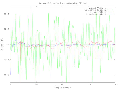
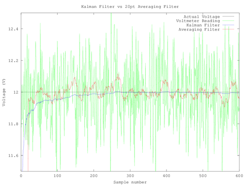
As you can see, I had huge noise and the constants and predictions I chose beforehand were pretty bad:
e_meas=0.5
e_model=0.0001
x[n-1]=5V
P[n-1]=1V
but overall, especially in for many samples, the algorithm gets better and better.
Below is the Octave code I used:
clear all; close all; clc;
n=200;
%True Voltage
V=12;
Vactual=12*ones(1,n);
%Noise
Noise=stdnormal_rnd(1,n);
%measured voltage
Vmeas=0.2*Noise+Vactual;
%Plot the scenario:
plot(Vactual,'k')
hold
plot(Vmeas,'g')
%Initial voltage and variance prediction
xpred=5;
pprev=1;
ppred=2;
xn=[];
R=0.6;
Q=0.000000001;
%Initialize matrix coefficients
for k=1:n
%Measurement update
K=ppred/(ppred+R);
xn(k)=xpred+K*(Vmeas(k)-xpred);
pprev=(1-K)*ppred;
%Time Update
xpred=xn(k);
ppred=pprev+Q;
end
plot(xn,'b')
filtCoeff=ones(1,10)./10;
lp=filter(filtCoeff,1,Vmeas);
plot(lp,'r');
title("Kalman Filter vs 10pt Averaging Filter");
xlabel("Sample number");
ylabel("Voltage (V)");
axis([0 n 11.5 12.5])
legend("Actual Voltage","Voltmeter Reading","Kalman Filter","Averaging Filter");
print("-dpng","L200-10ptavg-R-0p5.png");
Anywho, sorry this one was relatively pictureless. I think the math is amazingly beautiful though. In essence, we have a system that has memory since all of the new variables are derived from all previous values calculated, and yet we only use a few variables to accomplish this.
And that, my friends, is the 1-D Kalman filter.
Happy holidays!
0 notes
Text
Intro to Image Processing, Filtering and the Gabor Filter

It has occurred to me that I've fallen behind on blogging duties--not that I think that anything here is totally revolutionary, but there's some interesting stuff in the world and I like the empowerment of knowing that we can all do it too! With that in mind, I'd like to start doing a little work on posting once every two weeks.
This bi-week, we'll be talking about some basic image processing!
So far as I have experienced, in DSP, everything is dealt with in terms of filters because, really, filters are just weighted discrete points added or subtracted from each other, which can define any function you could imagine. For now, we are only concerned with FIR (finite impulse response) filters.
What's in a Filter?
I'll show a few examples of the functions a filter can perform momentarily but, first, let's look at what a filter is and how we can apply it.
We have as an input, an impulse train that has a set of values given by x[n]. The filters we are looking at take the present and last M points from the input, weight them and then sum them together to give the present output. Just to get the terminology down, the filter is then an M-order filter of length M+1. So far, then, we just have that a filter is just an array that is M+1 numbers long. So ultimately, the filter can be defined as an impulse train M+1 units long with magnitudes equal to the values in our filter array (called filter coefficients).

To find the output of the filter at a given point, we just have to multiply the current and last M points by the filter coefficients and then add them together.

One neat thing about that is that you’ll notice you only need three functions to implement a filter: a time delay element (think shift register), a multiplier and an adder. The second great consequence is that despite its simplicity, the filter can perform all kinds of functions you wouldn’t expect.
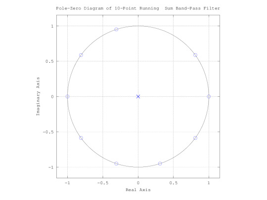
Examples
Just some of the functions we can do are, if we wanted to low-pass a signal, we might take the 10-point sum (the current point plus 9 previous points). Doing that, we end up with a frequency spectrum with a big hump at 0 rad/s, and some ripple going out from there. It is one of the simplest low-pass filters that you can construct.

We can see from the pole-zero diagram that at a frequency of 0, we have no zero.

By shifting the frequency response, we can get a bandpass filter and, since we are limited to normalized frequencies between -pi and pi, we can't really get a high-pass filter.
These filters can be complex or real.

Further, we can make a filter that will tell us the slope at any point. Recall from calculus the definition of a derivative:

Since we are dealing in the discrete-domain, by definition, the smallest dx is the sampling period t2-t1 and the derivative is then

Similarly, an integral can be represented as the sum of rectangles with height x[n] and width Ts. This is all precalculus stuff and makes sense intuitively.
Image Processing Intro
In image processing, we are no longer concerned with time or causality since we have two spatial dimensions and already know all of the input at once.
Just like the one dimensional filter, we use the M nearest points to determine the output of the filter but, this time, the filter is a 2d matrix.
Now let's take a look at a simple example.
Let’s say we have a photo like of this seasonally appropriate pumpkin. By applying a filter with dimensions 101 x 101 and filled with zeros except at its top left corner, we can shift the entire photo down and right by 50 pixels each.


We've shifted the entire picture down by 50 and left by 50 leaving a buffer that is undefined because, these pixels reference pixel values above and to the right of the picture dimension boundaries.
Of course there are more interesting things we can do. For example, you might have heard about a “gaussian blur.” What it really means is passing an image through a filter that has the shape of a gaussian curve. Since the step response of a gaussian is a more gentle slope up to a point, we can see that the gaussian will make all of our sharp edges where there is a sudden transition from white to black into a gradient.
Gabor Filter Basics
For this post, I’m going to do a little bit on gabor filter edge detection and, soon up, I’ll do another on object detection and tracking.
A gabor filter is a 2d filter with an impulse response given by a gaussian multiplied by a sinusoid.
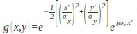


The x’ in the exponential is broken into an angular term which essentially defines what angle we will apply the cosine. We know from typical signal analysis that any signal, finite or otherwise can be decomposed into a set of scaled sinusoids. If we simply ran a gabor filter across an image in one direction (say theta=0 rad), we would find how well the image correlates with a sinusoid in one direction. By applying the filter at several different angles, we can get a “texture” of the image which helps in a whole variety of ways; textures of certain objects will be unique and so we can use them for object recognition; textures like edges can be detected in order to pull out shapes of objects in a scene; since the frequency of the sinusoid defines the spacing of features, the x and y determine the location of those features, and theta defines the rotational direction of the features, objects are rotation, translation, and scale invariant, making a very robust object recognition scheme.
Edge Detection
For now, I have only gone through edge detection. We will save everything else for another bi-week.
Consider a gaussian with a standard deviation of 1 and a sine wave at 1 rad. Since we are speaking of the spatial domain, the “rad/s” unit doesn’t have much significance. Instead what we are really concerned with is what we consider a second. The filter is a 14 x 14 array with nonzero values between 2 and 10, meaning the majority of the filter is held within these values.
A sine wave is essentially a step. Depending on how quickly it rises, and how large it spans, we can see that, if we correlated a step with the 1d version of this filter, we can get a high correlation.

Now, by applying the 2d filter across the entire image, rotating, and then repeating the application, we can get all of the steps in the photo. We can even tune the filter to more appropriately encapsulate certain transitions by lowering the frequency to encapsulate slower transitions and increasing it to pinpoint very high contrast areas.
For the sake of illustration, I did a quick one using a webcam and some Octave (open source Matlab for Ubuntu-types).


By averaging all angled frames together, we get a composite that highlights high contrast areas.
Fortunately, we definitely got my shirt but, unfortunately, it looks like lines of my face weren’t as prevalent and the curtain rod and ceiling corners were also high contrast.
We will come back to this in the future, but for now the edges have been detected! Now we just need to apply some filtering to smooth it, and create an algorithm to pull out objects. Piece of cake!
0 notes
Text
Wireless Power Made "Easy"
Whoops, here's a how to I needed to migrate from my old website!
I did mention that love inspires the greatest creations right?
Allow me to be mushy for a second.
My girlfriend is a great photographer (if you don't believe me, check it out) and she takes billions of pictures of me whenever we go adventuring. She shows me her love by sorting through those billions of pictures and not posting the 90% of those that show my many bad sides (I've been told I have a neck like an ostrich) so I thought I would repay her with the best I can give her in electronics.
Back in February, I gave her a half of a present: a necklace. And while my craftsmanship is far from "cute" by girl standards, it was one half of a PRETTY DAMN complex project. Artists will paint, poets will write sonnets, but I gave her my version of love: wireless power.
Now at the time of this writing, it's been about 4 months since last Valentines Day but, since then, I got a chance to study and get a scope and a degree so I figure it's about time to finish this thang! Brush up on your physics and diff eq's cuz this one is packed with some elegant equations.
This one's for you Linda Wong!

VARIATIONS
There are a bunch of ways to do wireless power in electronics. Now, there are the obvious ones (light, sound, heat, etc) but these all have the downfall of being annoyingly obvious. I wanted to astound her by lighting an LED without a solar cell dangling from her chest or shooting light/sound/heat at her.
EM waves lend a generous hand here. In the world of wireless power, they're the most elegant and most heavily researched at the moment since they don't need direct line of sight and aren't obvious.
This'll be the first in a series of three posts. This post will be about using magnetic fields to send power, next up will be electric fields, and finally we'll get to the big kahuna--EM waves.
MAGNETIC COUPLING
In magnetic coupling, there are three important functional blocks that we should focus on: generation, reception and loading. I know I know, that should be pretty obvious but we're starting basic.
Generator: needs to generate a changing magnetic field (we'll get to that shortly.)
Receiver: needs to receive the magnetic field and condition the signal for the load.
Load: Just is. But ultimately its dynamics affect how well we can deliver power to it.
Let's take a deeper look into each one.
GENERATOR COIL:
Generating magnetic fields is not hard at all. I'm sure you've all wrapped magnet wire around a nail at some point in your life, connected it up to a battery (really a bad idea) and then found out you just made an electromagnet! If not, go do it! But make sure to only touch the terminal of the battery for a little bit because everything gets very hot very fast.
A wire does just the same thing. In fact, the whole reason that an electromagnet does what it does is because of the magnetic field that each wire is setting up. The magnetic field of a current carrying wire looks something like this:
You can see that, as you go radially outward from the wire, the magnetic field drops off. Also notice that the magnetic field is in the form of a loop. Maxwell's equations tell us that there's no such thing as a magnetic monopole, i.e. magnetic fields can't spring from a particle like an electron does with an electric field. Instead, they are continuous and end where they begin and vice versa!
Now, we said "current carrying wire" because magnetic field only springs up (in electrodyamics/statics) from a current running through a wire. In fact, this is a lot like how an electric field only springs up from a potential. In fact, we're talking about analogous things! Ampere's law tells us that the current and magnetic field around it are related by

meaning if we drew a path around the wire (any ol' path) and summed the product of components of the magnetic fields that are parallel to the path and a differential path segment, we can get the current that we enclosed. This is enlightening because it shows us that if we picked a small circle around the wire (like the black one in the picture above) and a large one like the gray one around it, since the magnetic field is parallel at all points to the path, Iencl=B*L where L is the length of the circles. Also, since we know Iencl is the same for both circles, B*L for the small circle is the same as B*L for the large circle. The length of the small path is obviously smaller so it must have a larger B than the large circle.
By changing the geometry of the wire, we can shape the magnetic field we want to come from it so let's go with a loop since it's all right and relevant.

Here, the red arrow represents some current running through the loop and black arrows represent the magnetic field. All of the arrows in the middle will be the sum of the interactions between every magnetic field around the loop. That means, that the arrow in the middle will be nearly straight (though never exactly) and the field near the middle will seem like a beam for relatively small distances.
Now I know what you're thinking: "uh oh, this looks vaguely inductorish..." but you're wrong. Rest assured, it's VERY inductorish. By definition, inductors use current to set up magnetic fields that counter sudden changes in current. It just so turns out that these magnetic fields are super useful to us since we need to make these fields!
From Ampere's Law, we get a pretty cool little tip: by increasing the current through the wire, we get a bigger magnetic field. Let's say we want to double the magnetic field at a distance R. Well, that's easy, we just double the current, I, through the wire. The problem is that, as we increase current, we get a lot of heat in the wire and heat means energy loss from electron collisions and, hence, inefficiency. We can understand this by looking at the power equation and Ohm's Law:

and

so

Since we know there is some internal resistance to any length of wire, however small, as current rises, there's a significant power loss increase. If we double current, we quadruple power loss and tripling current yields 9 times power loss(!).
Instead, if we used a two turn coil of wire, and put them very close together, we get, approximately, double the current enclosed in a loop with radius R shown in the cross sectional top down view of the coil.

This is great! In fact, it means that our magnetic field is proportional to the number of turns on the inductor. Furthermore, the bulk of our magnetic field is concentrated in the center so we have something of a beam that we can send toward the receiver. Finally, we've doubled resistance since we doubled the length of wire but, again looking at the power equation, we only get double the power loss as opposed to quadruple.
There are a few things we oughtta consider when we're making our transmitter coil though and they are all the things we EE's dread about using inductors:
Multiple turns of coil mean greater inductance and magnetic field but more resistance
By coiling the wire, we end up with several "parallel wire" (think parallel plates) capacitors which manifest themselves as a parallel capacitance
These are the non-idealities of the inductor and led one of my smartest circuits professors to say "if you can use a capacitor instead of an inductor, DO IT."
Well, these are just things we'll have to deal with with our magnetic generator though since inductors are just so damn good at magnetic field generation! Besides, inside every non-ideality is a chance to learn!
I won't go into the details of why until later in this post, but large wires are key to dealing with (1). The reason isn't just because there is low internal resistance to a large wire, but actually has to do with frequency. To deal with (2), larger spacing between wires and a smaller coil area gives us lower capacitance since (roughly)

but at the sacrifice of inductance since the magnetic field is smaller as distance is increased.
The inductor will also need some driving circuitry but we'll get to that when we get to building!
RECEIVER COIL:
Now that we have a pretty sturdy way of developing a magnetic field, we'll need to turn that energy into something handy to us EE's, i.e. voltage/current. In order to totally understand what we'll receive, we need to go into some more inductor stuff. Stay with me though because these all play a pretty keen role in our efficiency!
Magnetic flux φ is the total magnetic flux density (B=μH) passing through a surface.
We represent it by
which makes total sense; knowing magnetic field is fine but knowing how much actually flows through a surface will give us the ability to tell how much that specific surface is being influenced by the magnetic field.
You've probably heard of two types of inductance: self-inductance and mutual inductance. Self-inductance is the magnetic field that runs through one loop that affects its own current.
Think of the magnetic field as a flywheel attached to a motor. A flywheel is just some heavy mass that you put at the end of a shaft. It takes some effort to get the flywheel turning but once it does, you can cut the power to the motor and it'll continue tuning before it loses its momentum. If you try to speed it up after it's turning, you'll have to put in more energy. To slow it down, you'll have to sap some of its energy.
The same thing is true of self-inductance. The magnetic field, as a flywheel, will take some of the energy you apply to it to maintain a magnetic field. In order to get the magnetic field going, you have to spend some energy from the current and that is where (self-)inductance comes from. Magnetic flux will try to keep current from flowing in or out so knowing it is important!
Mutual inductance is the inductance another coil has in response to the magnetic field that goes though its coils from a powered inductor. The powered inductor is called a "pimary" and the one receiving the magnetic field is called the "secondary."
Now, since the primary is producing a magnetic field and we want to find the amount of mutual inductance it has with a secondary, we use the flux equation to find the flux in the secondary due to a magnetic field from the primary.

We know from Faraday's Law (after a lot of simplification) that
(partial derivatives because B may vary with space as well).
This is great! We know that if dB/dt=0 (magnetic flux density doesn't change with time) there is no voltage developed. That means our generator better give us a changing magnetic field otherwise we'll have no power transfer.
Conversely, if we have a constantly changing magnetic field made from varying the current through the primary, we can develop a voltage across the secondary coil wires!
MAKING A COUPLE COILS
I didn't go into the tansformer equations because we have something of an imperfect transfomer. I'll show you what I mean in a bit.
First, make a couple coils. Any ol' coils will do! I used a large primary because I was interested in shooting a wide area and catching it with a smaller device, pretty similar to what we'd do in a practical scenario. They should be pretty big conductors so that you have to worry less about internal resistance. Just for the sake of experimentation, I wound two coils, one with three windings and another with four.
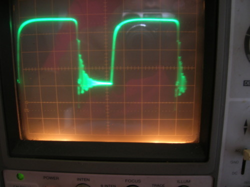
Now that we've done that, let's hook it up to an oscillator. I was dumb in the beginning and made a very low variable frequency oscillator from inverters that made a squarewave oscillator. The frequency response is terrible. From low to high frequency, it goes from this:
(5Vpp. Notice the rise and fall times)
to this:

(still 5Vpp)
to this:
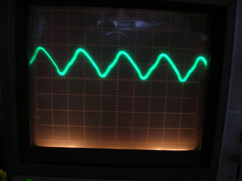
(about 1.5Vpp)
And so there I was, bummed that my oscillator circuit sucked. If the secondary had resonance at a high frequency, I would only have 1.5Vpp that I could deliver to it. For the hell of it, I decided to hook it up to the primary and see what came out at high frequencies. That's when everything became fuzzy:
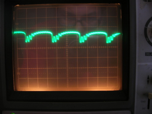
"Hmm..." thought I. What if we turn down the fequency:
Zoomed in and taking out the square waves, it looks like this:
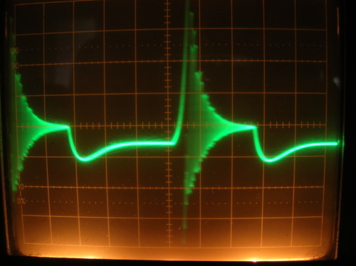
SPRINGS, INDUCTORS, AND DIFF EQ'S:
The first thing that hit me (which I hope hit you too) was "hey! That looks like damped harmonic motion!" You remember, it's all this jazz:

where, after we give a mass on a spring a tap, it starts oscillating, eventually degrading its amplitude toward zero exponentially because of friction, drag, etc. Here's why the two are similar.
The sum of forces on the spring are

where a is acceleration, v is velocity, and x is position of the mass m, k is the spring constant, and bv is the term that affects damping (propotional to velocity). Setting to 0 we have:
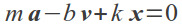
.
Since a is the second derivative of x and v is the first derivative of x, this all becomes a function of x(t) with x changing with time.
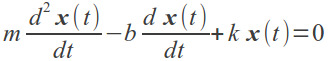
Notice that without the bv term (which represents the damping factor) we've got an oscillator that goes on forever since, a solution for x(t) is the sine or cosine function. With it, we'll have to remember some differential equations. For now, let's just see why our system behaves so similarly. Remember, this is a differential equation with a -b*dx/dt term for damping.
Now, here's a non-ideal inductor whether it is on the transmitting side or receiving side:
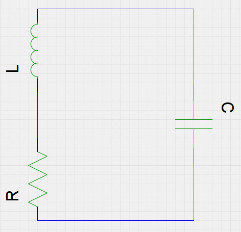
since there is an internal capacitance between windings and an internal resistance depending on the length of the wire.
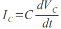
We know that the current into any one component is the same through any of the other components since it is one loop, and we know that the current through the capacitor (and the resistor and inductor) is
We would like to add all of the voltages since the sum of voltages in a loop is 0 so we start with the resistor which has voltage

and the inductor

and we'll leave Vc as Vc for now.
The sum is then
BUT WAIT! I is a function of the voltage Vc which changes with time so this would be waaay better rewritten
NOW compare that to the spring equation! We took Vc since it's the voltage across the terminals of the inductor whereas the actual inductance L in the diagram is the theoretical inductance that we should see.
Let's solve for Vc(t). Keep in mind through all this calculation, we're doing this to find the values internal to our inductor (R, C, and L from the schematic).
Just observing the waveform, we're obviously looking for a sinusoidal function multiplied by an exponential. The Vc's and derivatives are then


Putting that all together, we've got this:

which looks pretty ugly. But, luckily, we can simplify it a bunch by looking at particular instants in time. For t=π/2ω, all of our cosines become 0 and we can solve for a:

Now, taking t=0 and subbing R/2L for a, we get


One more equation to add is

This is super handy because, if we add an external capacitance in parallel with the inductor, the resonant frequency changes since the tank becomes:
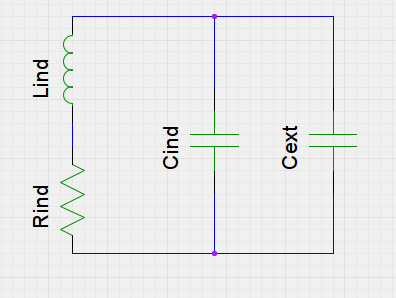
so our new equation is
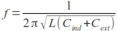
If we try two different capacitors for Cext, we can solve for everything in the square root and solve for L and Cind with two equations:

I solved for mine and got L=2.217uH and Cind=2.855nF. Then I took the voltages at the peaks and troughs of the oscillations we saw earlier on the scope and put them into google spreadsheet yielding:
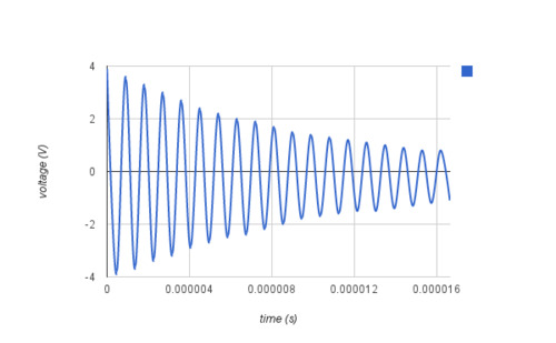
Since I know the frequency is set to somewhere around 1MHz (1.111MHz thereabouts), the ω (angular frequency) is known. If we take a couple peaks, we can solve for the exponential multiplier by fitting R/2L, and then just multiply by cos(2*π*1.11MHz), we can get an idea for what the internal resistance is! We can't just use a multimeter since they usually don't have enough precision. My R=0.43Ω and it gave me this beautiful curve:
where the blue curve is the one we found though experiment, red is the exponential, and yellow is the curve we calculated.
So that's why it looks like a spring and that's how we can find the values inside the inductor.
For the sake of being thorough, here's the circuit for the oscillator taken from a Fairchild app note. It's worth it to build, if for nothing else, just to get why all this is so interesting! Also it's nifty for finding the resonant frequencies of the primary and secondaries!

MAKIN THE RIGHT KINDA OSCILLATOR
So it's clear we need a faster oscillator with better frequency response. For me, time was a component so I ended up having to use a crystal. Maybe we'll make an oscillator some other time (I've only done 555's and an astable oscillator for LED flashing so this WILL happen!).
Crystals are pretty simple but they have poor output impedances. The specific crystal I have is also powered by 5v (a rating that is somehow absent from batteries) so I used an LDO and a common emitter amp to up the voltage and current headroom for the primary coil. This is about as simple as it gets and sacrificed a lot of the work I did to find efficiency but sometimes work has to be sacrificed for time.
Here's the final circuit I used:
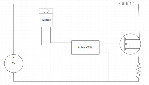
I know, I know, after the fanfare of physics, this is all the circuit that I needed. But the more ya know right?
There's another aspect to it being "just this simple"...

...it works!
And, as ghetto as it is, she loves it. Photo credits of that last picture: Linda Wong.
1 note
·
View note
Text
New Theme and how to add text posts to hasaportfolio

Hello, hello world!
I know I haven't been around much these days but the electronics and hacks have still been ripe for the pickin'!
So you might notice there's a new theme here at Alex Mo Tech! I picked it up from http://hasaportfolio.com/. It looked JUST how I wanted. The problem? It's for art types and only supports photos and videos. Nuts.
After a good night of tweaking, I finally got it to support text posts and this is how.
Download from http://hasaportfolio.com/ and install on tumblr (instructions on the site how to do this)
Copy the section from {block:Photo} to {/block:Photo} and paste it right above {block:Photo}
In your copied {block:Photo} change the block name to {block:Text} and {/block:Text}
You'll see a block of code that says:
<img src="{PhotoURL-250}" alt="{PhotoAlt}"/>
<div class="box-caption-text">{Caption}</div>
<a href="{Permalink}" class="box-caption">#</a>
The {Caption} is what will display when you mouseover the picture and the {PhotoURL-250} is the cover photo for a picture entry. Since a text post has neither, they will both turn out blank and we will need to change them. I changed {Caption} to {Title} so that it showed the Text entry's title on a hover.
For the "<img src" bit I went through a bunch of different options, trying to pull the first image from {Body} but it looks like once you read from {Body} it just messes everything up. Instead I put in this code:
{block:HasTags}
<span class="tags">
{block:Tags}
<img src={Tag} width="250px" />
{/block:Tags}
</span>
{/block:HasTags}
which just picks out your tag and uses it as an image source.
Add a tag to each text post with the URL to a photo
And that's it! If you're using my code (too simple to even really be called "mine") and you want to modify it, make sure to use spans just to make sure there aren't any unwanted lines above the thumbnail.
Also, I've tested with non-URL tags before and after the image URL and Tumblr seems to have no problem with it.
So, here's to a new look! Enjoy!
1 note
·
View note
Text
Welcome to the family...
THE KIKUSUI COS5021!
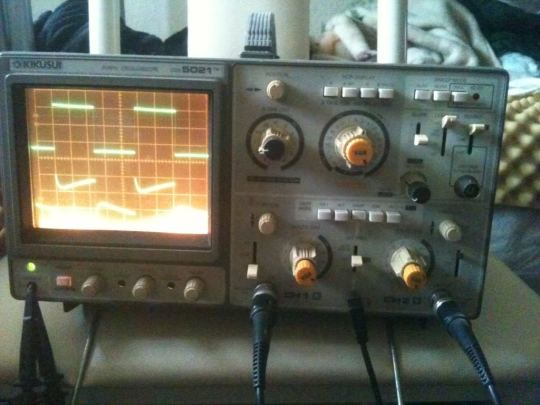
She's about 40 years old, samples at 20MHz, and runs on an ol' CRT, but she's my first and only cost me $20! (INSERT BLATANT AD FOR CRAIGSLIST)
This is really as cheap as they come unless you head on over to a swap meet or get it free from a campus near you.
With new oscilloscope in hand, expect even better How To's and projects!
I've wanted to do a lot more in the way of high frequency physics in my projects and, thanks to my new baby, you'll get an eyeful!
Stay tuned this week for about the simplest wireless power setup you can imagine!
0 notes
Text
T2E: Learning SPI through accelerometers!
Ever since the Wii came out, accelerometers have hit mainstream and FAST.
Last week, we got a chance to get a start on USART which is nearly set up for you on the Arduino. This week, let's take a look at a serial communication standard called SPI and get an accelerometer working to boot!

Before we take a look at how to use this thing, let's think about what we can do with it.
An accelerometer, as its name so obviously implies, is all about acceleration along each of the axes. The accelerometer we're using is a 3-axis which means it can measure acceleration in X,Y, and Z directions.
A quick recall of some mechanics and we realize we can get, not only the acceleration, but the velocity and position from this data by just finding the integral over time! Furthermore, since we have the direction of acceleration, we can find every aspect of motion of possible interest about the device!
We can even find the tilt of the thing, but we'll get into that later.
GETTIN' OUR ELECTRONICS ON
The device we're using today is the MMA7455 3-axis accelerometer module from Parallax. Here's where the axes are and the pinouts:

It works in a really interesting way with swinging capacitances and MEMS technology (that's MicroElectroMechanical Systems for those who don't know which mean the smallest feature size is on the order of microns!) but we'll chalk that up to black magic since, for now, we're only interested in interfacing and knowledge of how it works isn't really necessary in the same way that satellite positions were for GPS.
We'll go ahead and leave n/c and INT2 disconnected, but the rest we'll use. The INT1 pin is important to this specific chip while the rest of the pins are all for either power or communication standards which we'll cover in a bit.
Getting a Handle on the Chip
INT1 & INT2 are configurable interrupt pins which means they can serve a few different purposes if we like. The device has a few different modes:
standby -power is low and measurements aren't taken
measurement -the device takes measurements on all three axes and stores them until an axis' acceleration is read and then it re-reads
level detection -if the acceleration goes over a certain level, an interrupt pin is fired high
pulse detection -it senses a "tap" or even a double tap
The INT pins can be configured to go high whenever a tap is sensed, a double tap is sensed, a level is crossed or a measurement is finished!
We want to configure it so that it'll tell us when it's done reading the axes so we'll just configure INT1 to be fired whenever the DRDY (Data ReaDY) bit is switched. Also we have to tell it we want it in measurement mode. These are all accessed through the hex register $16 which has these bits:

BE EXCITED! We're talking on a bit level--exactly what the system understands. Whereas most of our projects are in some extracted language, we'll be directly accessing bits and registers using a microcontroller!
Okay, that note of glee aside, we have a lot of options with this chip. Data comes in 3 flavors: +/-8g, +/-4g, or +/-2g which means we can measure anywhere from 2 times the force of gravity in the + or - directions to 8 times the force of gravity in the + or - direction. Also, we can get all of our data in 8-bit precision (divide up the g range by 256 discrete parts of the full range) or 10-bits of precision in the case of 8g (1024 discrete parts).
As an example, let's say we chose 2g's at 8-bit precision. This means we have +/-2g's (4g's total) divide by 256 or 0.0156g's in each possible measurement. That means if we put it through an actual acceleration of 0.043g's, we would actually round to the nearest multiple of 0.0156 which is 0.469g's.
What will our Mode Control Register look like if want to do +/-2g's in measurement mode using 3-wire SPI with the INT1 pin for when our data's ready?
I hope you got 01100101!
I think we all get it so let's move on to SPI mode.
I SPY a SPI
Sorry, I dig hokey titles.
SPI (Serial Peripheral Interface) is a form of serial communication that you can use to talk to a bunch of devices. Usually, in this scenario, we call the device that's controlling the "master" (the microcontroller) and the devices it is controlling the "slaves" (other devices). Here's the way it works:
Our master is a guy that's shouting commands. He's a rambler so he's always talking, maybe not specifically to any given device. Then when he says "SLAVE #1! FIND ME MY X-AXIS ACCELERATION, Y-AXIS ACCELERATION, AND Z-AXIS ACCELERATION!" Slave #1 is obligated to respond "0.6g's sir!" The other Slaves didn't hear their name so they know they don't really have to listen unless the master says .
That's how SPI works! It's sending commands that all of the devices can hear but they don't listen unless they are addressed. The layout is like what you see below.
Whenever the microcontroller drives the CS pin low for the device it wants to talk to, that device listens. Otherwise, it will keep the devices it doesn't want to talk to high. Each bit is cycled in using the CLK pin. So the basic scheme is set a bit to the output, clock high, the device stores the bit, and then the clock goes low and the device interprets the bit. Similarly, when the uC wants to read information from a device, it'll clock high, read the bit, then clock low so the device knows to send the next bit. The very cool part of this is that you only need n+4 pins to control n devices since the 4 pins for control are shared by each device!
An even more cool thing is that a lot of devices can work in 3-wire mode. Here, the pins are CS, CLK, and I/O where I/O is one pin! The way this works is that the master yells a command to the device that it's either gonna read to or write from one of the registers in the device and sends an address for the register it wants to read or write. If it sent the read command, the uC then listens on the I/O pin for a response. If it sent the write command, the uC then writes the information that it wants to set to the register.
Here's a picture from the datasheet to show ya what I mean:
Each of the "A[n]" bits is an address bit and the "D[n]" bits are the data bits that are either read or written.
Remember that CS has to be low this entire time!
Also, so that you don't bang your head against the wall, notice the first bit in the address byte says "R/W." For this bit, sending 0 first tells the accelerometer we're gonna read information from the addressed register and sending a 1 first tells it we're gonna send information we want set to the register. Also youll notice that, with the R/W bit included, the address byte is only 7 bits long! Actually, that little gray square between A[0] and D[7] is a parity bit and it can be anything you want! It just makes sure that the byte is 8 bits long so go hogwild: 0, 1, set the gray bit to anything your heart desires.
PUTTIN THE CODE TO WORK
Okay, so there is a SPI library in Arduino but how much ownership can you put on a product that you didn't build yourself?! I like the idea of a ground up approach so let's go ahead and code right quick.
Before anything, let's figure out how we're gonna set this up. We'll want to use the serial monitor so pins 0 and 1 are a no-go. Let's use pins 2-5 instead!
#define CLK 2
#define DATA 3
#define CS 4
#define RDY 5
Now there are a few important registers. The ones we're interested in are XOUT8(0x06), YOUT8(0X07), ZOUT8(0X08), the status register (0x09), and the mode register (0x16).
#define XOUT8 0x06
#define YOUT8 0x07
#define ZOUT8 0x08
#define SREG 0x09
#define MODE 0x16
We'll want to store the values of X,Y, and Z:
signed char Xval=0x00;
signed char Yval=0x00;
signed char Zval=0x00;
And we'll want to set up our inputs and outputs.
void setup()
{
pinMode(CLK,OUTPUT);
pinMode(DATA,OUTPUT);
pinMode(CS,OUTPUT);
pinMode(RDY,INPUT);
digitalWrite(CLK,LOW);
digitalWrite(DATA,LOW);
digitalWrite(CS,LOW);
Serial.begin(9600);
writeInstruction(MODE,0b00100101);
}
That last line initializes the accelerometer the way we said earlier.
Now, we know we're gonna have to read and write a whole bunch so we oughtta make some functions that do just that!
Writing
For a write, we know we need two pieces of information: which register we want to write to and what we want to write to it. It doesn't have to return anything since it's just a write command so let's do this!
void writeInstruction(char address, char msg){}
We know address and msg will be bytes so we can use char here.
Now we're gonna send the address first. As the picture showed, the address is only 6 bits long and we need to format it the way the accelerometer likes to see, i.e. with a 1 at the beginning showing we're writing and some extra bit at the end.
address=address<<1;
address|=0b10000000;
The << operator is called the shift operator because it shifts a byte over by whatever number is to the right of the operator. The |= operation is kind of like +=. It will OR each bit in address with the binary number 10000000 and then store it into address. Since anything ORed with 1 = 1 and anything ORed with 0 is whatever was originally at that bit position, this operation means we're only making the MSB 1 if it wasn't already.
Now, we have to shift out each of the bits from left to right and send them to the microcontroller. We know there'll be 8 bits for every full address byte so let's use a for loop.
for(int i=0;i<8;i++)
{
if(address&0b10000000)
digitalWrite(DATA,HIGH);
else
digitalWrite(DATA,LOW);
address=address<<1;
digitalWrite(CLK,HIGH);
digitalWrite(CLK,LOW);
}
The if statement checks if the first bit is a 1. If it is, it'll send a HIGH to the DATA pin (and otherwise LOW). Then it shifts the address byte that we made, clocks once and then returns to the top. Easy as pie.
For the msg that we sent, it's even easier! We don't need any conditioning so we'll just do the same for that byte:
for(int i=0;i<8;i++)
{
if(msg&0b10000000)
digitalWrite(DATA,HIGH);
else
digitalWrite(DATA,LOW);
msg=msg<<1;
digitalWrite(CLK,HIGH);
digitalWrite(CLK,LOW);
}
Now stick it all in the writeInstruction function and give yourself a pat on the back because that's DONEZO.
READ
For the read function, we'll send it an address, but we'll want a value back. Specifically, we want the X,Y, and Z acceleration values back. Since this is a signed 8bit value, we'll use a signed char as the return type.
signed char readRegister(char address){}
Again, we condition the address byte, but this time, instead of setting the first bit, we clear it to 0 since that implies we mean to read a byte.
address=address<<1;
address&=~0b10000000;
Just as before, we send out the address bit by bit:
for(int i=0;i<8;i++)
{
if(address&0b10000000)
digitalWrite(DATA,HIGH);
else
digitalWrite(DATA,LOW);
address=address<<1;
digitalWrite(CLK,HIGH);
digitalWrite(CLK,LOW);
}
which shouldn't be new to you since that's what we did in the last function!
Next we have to set the DATA pin to read, set up a variable to hold the data we read, and then get the data bit by bit and put it into the variable we created. I called mine temp since I'm creative, but not THAT creative. Then, we set the pin back to output and return temp!
pinMode(DATA,INPUT);
signed char temp=0x00;
boolean currentBit;
for(int i=7;i>=0;i--){
digitalWrite(CLK,HIGH);
currentBit=digitalRead(DATA);
temp|=currentBit<<i;
digitalWrite(CLK,LOW);
}
pinMode(DATA,OUTPUT);
return temp;
So the loop goes backward (since we're getting the most significant bit first from the MMA) and temp is |='ed with a byte that is essentially the read bit shifted over to its correct position. This way, none of the bits that aren't in the currentBit's position aren't affected.
Stick that code into readRegister() and you're almost home.
The loop is then just getting the values, and then printing them in the serial monitor.
void loop()
{
Xval=readRegister(XOUT8); //get X val
Yval=readRegister(YOUT8); //get Y val
Zval=readRegister(ZOUT8); //get Z val
Serial.print (Xval,DEC); Serial.print(",");
Serial.print (Yval,DEC); Serial.print(",");
Serial.println (Zval,DEC);
}
Since the Xval is some randomazz byte in binary (2's complement for negative), we use Serial.print(VALUE,DEC); so that the number is converted into some decimal value. I used CSV formatting and I got this neato graph!

Here, I just waved the thing up and down twice in the Z-direction (yellow), X-direction (blue), and then the Y-direction (red).
The Z-axis acceleration is offset because the damn thing can measure gravity! In fact, it's sitting at around 64. Since we chose signed integers to represent the data, and you'll recall this thing is measuring +/-2g's at 8 bit resolution (i.e. ~+/-127), sitting at 64 means that we're measuring 1g: GRAVITY!
This is another great advantage to the chip. If we can measure gravity, we can measure how much the device is tilted; if the X-axis was perpendicular to the ground, then we would get an offset of 64 on the X-acceleration measurement. Here's another graph from tilting it from the Z-direction to the Y-direction, back to the Z and then to the X-direction.

You can see it will go negative depending on which direction you tilt it.
So there ya go! You can read ALL movement data using the accelerometer! Of course there's a lot more to do. There's a hefty amount of noise from random vibrations in the room and the interpretation of all that data! Oi! Furthermore, you can communicate with the MMA7455 through I2C! But, alas, there's a fundamental text limit that one can read before their head explodes (that's why I try to keep my reading to a minimum) so we'll save that for when this guy goes into a project!
0 notes
Text
T2E: GPS
Hello hello again, Interweb!
It's time, now, for the first installment of a series called "Talking to Electronics (T2E)." In each post of T2E, we'll investigate how to communicate between microcontrollers and modules--everything from Speech chips to LCD screens to SD cards and beyond!
As the title blatantly advertises, today's topic is GPS!

If you're interested in the theory, read on, dear traveler! Otherwise, go ahead and skip to "Talking to GPS," but I warn you, you're missing out on some pretty dope google draw pictures.
THE BASICS

GPS or Global Positioning System is a system set up by the U.S. Department of Defense that uses 24 satellites shooting radio waves in all directions. What we all know as GPS (as in "check the damn GPS!") is actually just a device that has a little radio receiver in it and some circuitry to draw a map on the LCD screen. The business end of things is the little radio receiver that looks something like this:
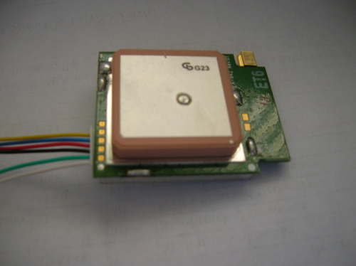
How does the little GPS do that? Well, like most of our projects, it has to do with some very cool math.
First off, we know the receiver gets its info from satellites sending signals at the speed of light. The receiver knows a few things about the satellites thanks to the information that they send. Each satellite sends an identification message along with its position. By the time the receiver gets a signal from a satellite, some time has passed. Given the amount of delay between the source and receiver and the fact that the signal travels at the speed of light, you can determine the distance between the two.
Kay, so we've got the distance between a satellite and the receiver. Now, let's say we're living in 2D land on a nice X-Y coordinate system. How many satellites do we need? If we have one, we've got

This is obviously no good! We can be anywhere along the circle! Let's add a bunch more precision with another satellite:
MUCH better, but now we've got two possible points. Add another satellite and:

Bingo!
This method is called "trilateration."
But life ain't so flat. Will 3D be much more difficult?
In 3d, here's how our one satellite looks. Keep in mind we're DEFINITELY on earth's surface so we need one less satellite (we're always a distance Ro from the center of the earth).

Okay, so if we get a distance from one satellite, we are somewhere along a circle on the earth. To see this, imagine a sphere intersecting another sphere; you get a circle formed by the intersection. Let's add one more satellite's worth of data.

Now, technically, there were an infinite number of ways for these circles to form and we could have ended up with the same situation as in 2D where we have two intersection points. However, we can shave off an extra satellite if we drop a point straight down from the each satellite to the earth, and form new circles from this point to the receiving point. We can do this since the satellites are at precise locations above the earth so their drop-down distance is exactly known.
If we just do a little Pythagorean theorem, we get A1 and A2!
Very cool!
For more very interesting information, check out this link at pocketgpsworld
TALKING TO GPS
I chose GPS kinda by accident and it turned out to be about the simplest thing to interface with!
Let's start with the Arduino way since we have nearly all the software setup for us and we've got a serial monitor to play with!
The RX and TX for the Arduino's USART module is broken out to Pin 0 and 1 so these guys are reserved for talking to the computer through the USB since we want to use the serial monitor. If, instead, we just piped the information to the processor, did some operations on it and output it somewhere without using the USB communication, we could totally use 0 and 1 on the Arduino. Instead, we'll have to use pins 2 and 3.
Now, with a lot of chips, you need to have a startup sequence, but the GPS is different. On power-up, it immediately starts looking for satellites and, once it has locked onto 3 or 4+, it'll start sending data immediately over its Tx port, so really, for now, let's just ignore the Rx port. This means we only need Tx, Vin, and Gnd! 3 pins! The datasheet shows that too!
Ok ok, this is a doing blog. Let's get into that!
Electronics
You don't by any means have to use the specific hardware I've got since nearly all the pinous and coding will be exactly the same!
I used:
1 cup PMB-688 SiRF GPS module
a pinch of Arduino Diecimila with an Atmega328 onboard
a little love.
As we said, the electronics is dead simple. Positive, ground, and pin2 (let's say for Rx on the Arduino side).
Bam. No extra components!
The real lifting comes on the programming end.
Programming
Okay, so we already established we needed two extra serial ports to connect through to get this thang goin so we'll use a library called "SoftwareSerial.h" It allows us to use USART on any of the pins. It goes like this:
#include <SoftwareSerial.h> //the library we want
SoftwareSerial GPSmodule = SoftwareSerial(2,3); //makes a SoftwareSerial object called GPSmodule with Rx at pin2 and Tx at pin3
That's all we need to get started!
Next, in the setup, we need a baudrate or a speed at which to communicate. Serial communication can take place either synchronously or asynchronously. This just means "with a clock" or "without a clock" respectively. In synchronous communication, one pin is designated a clock pin and it tells each device when a bit is being sent/received. We'll cover this in later projects.
For asynchronous, each device operates at a set speed. So let's say we turn on our GPS module and then start reading. We run into a problem! If they're just at some set speed, what's to keep the uC from reading the middle of a byte message instead of the beginning? Well, all the data bits are sandwiched between a start bit and a stop bit like this:
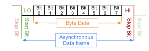
Now, if we see that a '0' followed by a '1' appears periodically after 8 bits, we'll know that they're the start and stop bits! These are called 'parity bits' and they'll be handy later.
Okay, so both the USART module and SoftwareSerial library take care of the parity bits so that we can take out the good stuff. Now we just need to setup the baudrate. The default for our GPS is 4800 so we'll assign the GPSmodule object that number.
void setup(){
GPSmodule.begin(4800);
Serial.begin(9600);
}
And then just readout the raw data:
void loop(){
Serial.write(GPSmodule.read());
}
SIMPLE non? In older Arduino we woulda said Serial.print(GPSmodule.read(),BYTE);. It's been a while since I used Arduino so this is kinda a mystery to me. My output ended up being:
ÿ$ÿGÿPÿGÿSÿVÿ,ÿ3ÿ,ÿ1ÿ,ÿ1ÿ2ÿ,ÿ2ÿ0ÿ,ÿ6ÿ6ÿ,ÿ2ÿ0ÿ0ÿ,ÿ4ÿ1ÿ,ÿ2ÿ3ÿ,ÿ6ÿ0ÿ,
ÿ3ÿ3ÿ9ÿ,ÿ3ÿ5ÿ,ÿ1ÿ6ÿ,ÿ5ÿ4ÿ,ÿ0ÿ9ÿ6ÿ,ÿ2ÿ8ÿ,ÿ3ÿ2ÿ,ÿ4ÿ8ÿ,ÿ1ÿ5ÿ7ÿ,ÿ3ÿ3ÿ*ÿ7ÿ8ÿ
ÿ
ÿ$ÿGÿPÿGÿSÿVÿ,ÿ3ÿ,ÿ2ÿ,ÿ1ÿ2ÿ,ÿ3ÿ0ÿ,ÿ4ÿ1ÿ,ÿ0ÿ5ÿ8ÿ,ÿ3ÿ1ÿ,ÿ1ÿ3ÿ,ÿ3ÿ4ÿ,
ÿ3ÿ0ÿ7ÿ,ÿ2ÿ2ÿ,ÿ0ÿ7ÿ,ÿ2ÿ5ÿ,ÿ2ÿ4ÿ6ÿ,ÿ3ÿ4ÿ,ÿ0ÿ4ÿ,ÿ0ÿ9ÿ,ÿ3ÿ0ÿ1ÿ,ÿ2ÿ8ÿ*ÿ7ÿ1ÿ
ÿ
ÿ$ÿGÿPÿGÿSÿVÿ,ÿ3ÿ,ÿ3ÿ,ÿ1ÿ2ÿ,ÿ2ÿ4ÿ,ÿ0ÿ9ÿ,ÿ3ÿ0ÿ8ÿ,ÿ,ÿ1ÿ0ÿ,ÿ0ÿ7ÿ,
ÿ3ÿ1ÿ9ÿ,ÿ2ÿ7ÿ,ÿ0ÿ3ÿ,ÿ0ÿ7ÿ,ÿ1ÿ3ÿ2ÿ,ÿ2ÿ5ÿ,ÿ3ÿ1ÿ,ÿ0ÿ6ÿ,ÿ0ÿ5ÿ2ÿ,ÿ*ÿ7ÿ6ÿ
ÿ
ÿ$ÿGÿPÿRÿMÿCÿ,ÿ2ÿ1ÿ1ÿ5ÿ0ÿ3ÿ.ÿ0ÿ0ÿ0ÿ,ÿAÿ,ÿ3ÿ4ÿ0ÿ0ÿ.ÿ6ÿ3ÿ6ÿ1ÿ,
ÿNÿ,ÿ1ÿ1ÿ8ÿ2ÿ4ÿ.ÿ8ÿ4ÿ7ÿ4ÿ,ÿWÿ,ÿ0ÿ.ÿ0ÿ0ÿ,ÿ1ÿ1ÿ1ÿ.ÿ1ÿ5ÿ,ÿ1ÿ7ÿ0ÿ4ÿ1ÿ2ÿ,ÿ,ÿ,ÿDÿ*ÿ7ÿDÿ
ÿ
ÿÿÿÿÿÿÿÿÿÿÿÿÿÿÿÿÿÿÿÿÿÿÿÿÿÿÿÿÿÿÿÿÿÿÿÿÿÿÿÿÿÿ
Which looks a little gibberish-y right? Let's take away all those "ÿ"
$GPGSV,3,1,12,20,66,200,41,23,60,339,35,16,54,096,28,32,48,157,33*78
$GPGSV,3,2,12,30,41,058,31,13,34,307,22,07,25,246,34,04,09,301,28*71
$GPGSV,3,3,12,24,09,308,,10,07,319,27,03,07,132,25,31,06,052,*76
$GPRMC,211503.000,A,3400.6361,N,11824.8474,W,0.00,111.15,170412,,,D*7D
Aaah, now we've got something a little more interesting!
The GPS just sends straight up text data in ASCII! Obviously we don't want all those ÿ's and we want our PROGRAM to work for US not for US to work for the program! So I converted the stream into integer (you can change between data types by using
(datatype) variable name : example (int) characterVariable
to get the integer value of the character. It turned out to be a bunch of -1's so I just took those out by adding
char received;
and using the loop:
received=GPSmodule.read();
if((int)received==-1){}
else Serial.print(received);
and everything was programagically switched to something like this!
$GPRMC,234345.000,A,3400.6283,N,11824.8435,W,0.00,95.49,170412,,,A*47
$GPGGA,234346.000,3400.6283,N,11824.8435,W,1,07,1.3,22.0,M,-33.9,M,,0000*57
$GPGSA,A,3,23,06,07,08,19,10,16,,,,,,2.8,1.3,2.5*3B
$GPGSV,3,1,12,13,76,094,33,07,60,338,31,23,45,129,36,10,39,262,31*7D
$GPGSV,3,2,12,08,35,289,29,19,31,107,27,03,28,064,32,28,18,220,18*74
$GPGSV,3,3,12,06,18,053,36,05,11,316,23,16,10,041,23,20,02,173,*71
$GPRMC,234346.000,A,3400.6283,N,11824.8435,W,0.00,95.49,170412,,,A*44
$GPGGA,234347.000,3400.6283,N,11824.8435,W,1,07,1.3,22.0,M,-33.9,M,,0000*56
$GPGSA,A,3,23,06,07,08,19,10,16,,,,,,2.8,1.3,2.5*3B
$GPRMC,234347.000,A,3400.6283,N,11824.8435,W,0.00,95.49,170412,,,A*45
Nice. I readout about 51 lines and found a recurring pattern:
$GPRMC,$GPGGA,$GPGSA, $GPRMC,$GPGGA,$GPGSA, $GPRMC,$GPGGA,$GPGSA, $GPRMC,$GPGGA,$GPGSA, $GPRMC,$GPGGA,$GPGSA, $GPGSV,$GPGSV,$GPGSV
a buncha times. Now what does each one mean? Whelp, they all happen to be a part of the NMEA standard. Here's are some of the more useful values we've got, but there are more details in the NMEA reference manual here.

Here, the only thing that's not so familiar is speed in knots. Since this was developed by the National Marine Electronics Association, it would make sense that speed is in knots or nautical miles/hr.
1 knot = 1.5078 mph = 0.51444 m/s
Also the angle with respect to true north means we get a nifty compass! Score!

In the GPGGA sentence, we get a whole bunch of altitude data. The mean sea level is a model of the Earth using area specific data and represents the 0 altitude point so, in this example, 22 m is the distance from a 0 sea level. The Geoid to Ellipsoid measurement is the difference between the Earth model as a flattened sphere and its height at hills and valleys. For more information on these values check the esri website here!
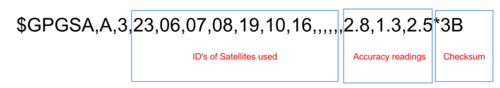
The $GPGSA line tells us the ID's of the satellites we're getting data from, and there are some accuracy readings following that to show the fidelity of the readings.

Finally, the $GPGSV line will give us some information about the satellites that the GPS got information from including the elevation (in spherical coordinates, the vertical angle), the azimuth angle (the horizontal angle in spherical) and the signal to noise ratio (SNR). There are four satellites per $GPGSV line and three lines giving a total of 12 satellites.
Isn't that a-friggin-mazing? You have the angle of a satellite and (essentially) their distance, so you could point DIRECTLY AT one. I dunno why but that's pretty astounding to me.
Anywho, this is one of those rare instances where we have SO much information that it's up to us what we want to pull! If we wanted, we could make an atomic clock, but it wouldn't be all that interesting. We could make automated cars, robots that move around the world, geocaching games, the possibilities are endless! In fact, we'll DEFINITELY see this again in a later project so keep your mind sharp and start goin places!

0 notes
Text
Project: NATCAR
So I happened into a design class at UCLA and it turned out I fell in love with robotics. By the end of the quarter, we ended up with this bad mamajama:
His name's Killbot and you can make one of your own!
In this series, I'll cover all the basics to get ya started!
Intro >
Overview >
Sensing >
AFE >
Motors >
Power >
Control >
0 notes