#drillingrigcontractoroilandgas
Text
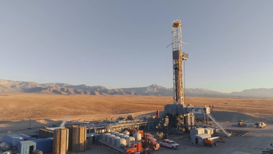
REDUCE WELLBORE PLACEMENT UNCERTAINTY BY UP TO 60% | H&P SURVEY MANAGEMENT
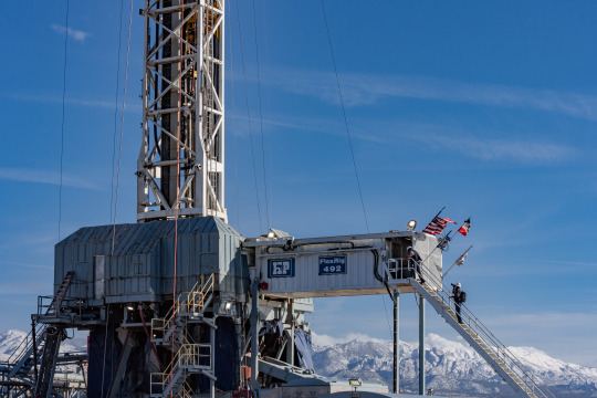
When drilling in congested fields, there is significant danger of catastrophic collisions with an existing (offset) wellbore. Apart from the economic damage of destroying two valuable wellbores, a collision may also result in a health, safety and environmental event. That is why many operators maintain anti-collision policies aimed at reducing the risk of such events. These policies define the safe distance that must be maintained between two wellbores to increase the separation factor (SF).
To increase the SF between a planned wellbore and its offset wells, the planned wellbore can sometimes be moved or shortened. However, these modifications to the well plan can result in suboptimal drainage and field development, stranded reserves, added drilling complexity or additional directional work. Instead of moving or shortening the planned wellbore, a more economical approach is to increase the positional accuracy by correcting survey measurements. The higher the confidence in their position, the more it increases the SF between the old and new wellbores - reducing the collision risk.
Therefore, before modifying the well plan to move the new wellbore to a suboptimal position, it is advised and has become widespread practice in the United States, to first increase the wellbore surveying accuracy as much as possible by employing enhanced survey management techniques. Well-established techniques of IFR, and advanced MWD analytics corrections reduce the wellbore placement uncertainty by up to 60%*.
Applying these techniques will significantly increase the SFs between new wells drilled in congested fields. Reach out to us if you are searching for your drilling partner: https://www.helmerichpayne.com/technologies/survey-management and contact us here: https://www.helmerichpayne.com/contact.
#rigcontractoroilandgas#drillingtechnology#helmerichandpayne#drillingautomation#drillingrigcontractoroilandgas
0 notes
Text
BY AUTOMATING SPEED, QUALITY, AND SAFETY H&P HELPS REDUCE TIME TO TARGET AND HUMAN VARIABILITY | H&P COLLISION AVOIDANCE

You plan your well to be safe, but when deviations from plan inevitably occur an updated analysis must be performed to confirm that the new execution plan is still safe. Traditional risk management processes can sometimes work against your desired outcome by being inefficient and creating frustration. They are also dependent on human variables that require more support and can have a high level of variance or bias.
H&P Collision Avoidance provides frustration-free anti-collision analysis that does not compromise time to target due to decision delay and removes the de-manning barrier required by traditional collision avoidance systems. BY AUTOMATING SPEED, QUALITY, AND SAFETY H&P HELPS REDUCE TIME TO TARGET AND HUMAN VARIABILITY HOW DOES IT WORK? Prior to drilling, Collision Avoidance is configured with well plans, survey programs, and all wells to be avoided.
While drilling, H&P Collision Avoidance monitors the Bit Guidance System for any indication of a new convergence plan. When a new plan is detected, it pulls the updated data on the wellbore position (and its uncertainty) combining it with the convergence plan. Using this combined data set, an estimate of the risk of drilling the convergence plan is produced. If this risk is above specified tolerance levels, then alerts will appear for the rig and interested parties, so that a management of change can occur. Know more about us here: https://www.helmerichpayne.com/technologies/survey-management or contact us at: https://www.helmerichpayne.com/contact.
#rigcontractoroilandgas#drillingtechnology#helmerichandpayne#drillingautomation#drillingrigcontractoroilandgas
0 notes
Text
ENHANCED MAGNETIC SURVEYING | H&P SURVEY MANAGEMENT

Tighter well spacing, multi-well pad designs, and longer laterals create drilling conditions with higher collision risk and the need for greater positional accuracy. Using high-accuracy In-Field Referencing (IFR) models will improve anti-collision separation factors (SF) by as much as 60% as compared to main field magnetic models used in standard MWD surveying. This not only reduces collision risk, but also enables more accurate well placement. IFR does NOT require additional downhole tools, on-site personnel, or rig time.
IN-FIELD REFERENCING (IFR) IFR is an industry-recognized, low-cost method for reducing wellbore positional uncertainty associated with MWD surveying. Applying IFR can significantly increase the SFs for wells drilled in congested fields. While H&P survey corrections do not require re-entry/re-surveying old wells, that option is available to further reduce uncertainty of previously drilled wells in congested fields.
Higher SFs will require fewer dispensations and reduce risk of well-to-well collision and lease line infractions. Reducing positional uncertainty also enables future in-fill drilling campaigns. Main field geomagnetic models used in standard MWD do not capture local crustal anomalies of the geomagnetic field. IFR is the industry-leading method of accurately predicting the magnetic field magnitude and direction for a geographic location and time. IFR relies on independently acquired measurements of the local magnetic field to accurately map regional variations caused by magnetic minerals in the Earth’s lower crust.
IFR improves MWD surveying by providing highly accurate reference directions for azimuth calculation. IFR also provides more accurate estimates for magnetic dip angle and total field strength, which enables more precise survey quality control and correction. Visit us here to know more about us: https://www.helmerichpayne.com/technologies/survey-management or contact us at: https://www.helmerichpayne.com/contact.
#rigcontractoroilandgas#drillingtechnology#helmerichandpayne#drillingautomation#drillingrigcontractoroilandgas
0 notes
Text
Driving Safety Forward: An Industry Panel Discussion | Moderated by Drilling Company H&P

How is the industry driving safety forward? Gain invaluable insights and be part of the movement for safer roads! Don't miss our enlightening panel discussion, "Driving Safety Forward," featuring HSE leaders across the oil and gas industry and moderated by H&P's Micah Backlund, Director, HSE North America Solutions. Together, let's champion responsible driving habits and work toward reducing accidents.
👏 A special thanks to our panelists: Jon Hamill, Oxy, Director, HSE U.S. Onshore Resources & Carbon Management Diana Lopez, Baker Hughes, VP, HSE & Service Delivery Clint Anderson, EOG Resources, Safety Manager Gabe Leal, Nabors, QHSE Director, Global Interested in more FREE safe driving resources? Visit this page to download a driving safety moment, printable stickers, and more: https://www.helmerichpayne.com/our-ap... 📖📚 Dive into our 100+ year history here: https://bit.ly/hpabout REVOLUTIONARY RIG DESIGN. 💪 Read about our award-winning FlexRig® Fleet designed for optimal flexibility, performance, and efficiency: https://bit.ly/flexrig-fleet 🎥 Watch our Flex 3 in action: https://bit.ly/flex3-move WANT MORE AUTOMATION?
⏳🔃 Our advanced Rig Floor Automation technology can help you achieve better drilling outcomes: https://bit.ly/rigfloor-automation 🤝TALK TO A RIG SPECIALIST TODAY! Contact our sales team: https://bit.ly/sales-contacts.
#rigcontractoroilandgas#drillingtechnology#helmerichandpayne#drillingautomation#drillingrigcontractoroilandgas
0 notes
Text
Achieving ISCWSA MWD+IFR1 Tool Codes Without Airborne Magnetic Surveys
Accurate wellbore placement and collision avoidance are increasingly important in today's tightly spaced horizontal wells and congested fields. Modern well plans incorporate hydraulic fracture geometry, reservoir characteristics, and other factors to maximize reservoir extraction while minimizing drilling costs and safety risks. Directional surveys that have minimal uncertainty are crucial to drilling the optimized well plan.
This work enables more accurate directional surveys and wellbore placement through site-specific high accuracy magnetic models. Under the Industry Steering Committee on Wellbore Survey Accuracy (ISCWSA) error model, the use of In-Field geomagnetic Referencing (IFR) dramatically reduces some of the largest sources of error in wellbore location. Unfortunately, IFR can be expensive or out of reach for smaller or less mature basins because of the high cost of flying or purchasing high-resolution aeromagnetic surveys.
An economic and timely alternative has been developed, strategically taking ground magnetic measurements at sites along the wellbore(s) with absolute instruments, combined with a high-definition global magnetic model to produce IFR at the pad scale. This method was tested in the Denver-Julesburg Basin in Colorado. A small survey team collected ground magnetic measurements over a typical pad design in one day. The data was then processed and combined with a high-definition global magnetic model to produce IFR corrections locally for the pad.
This study demonstrates that the procedure reduces the horizontal wellbore position uncertainty by 46% for the study area and more generally from 15 to 50 percent when compared to standard MWD (Measurement While Drilling) survey technology. Furthermore, this method was compared to a typical IFR model created from airborne measurements. Read out the full tech paper here: https://www.helmerichpayne.com/resources/technical-publications/achieving-iscwsa-mwd-ifr1-tool-codes-without-airborne-magnetic-surveys or directly contact us at: https://www.helmerichpayne.com/contact.
#rigcontractoroilandgas#drillingtechnology#helmerichandpayne#drillingautomation#drillingrigcontractoroilandgas#drillingrigcontractor
0 notes
Text
Recovery Control - Closing the Loop in Automated Control Systems
Drilling process automation has been a trending topic within the technical community, most recently discussed in SPE-212565-MS (Cayeux et al. 2023). Recovery control - specifically in the case of motor stalls - is not only integral to consistently completing automation control system execution, but also building confidence for the control system users and ultimate automation benefactors. Predicting, preventing, detecting, mitigating, and recovering motor stalls through automated recovery control solves an issue affecting most operators, contributing to additional bottom-hole assembly (BHA) damage and unplanned trips.
The recovery control system was designed with six major process control interfaces, two of which occur during on-bottom drilling: drilling while rotating and drilling while sliding. Each control interface is a means by which an external system can control the rig tools in a coordinated fashion, managing what control is currently active and ensuring the driller can ultimately assume control at any given time. The recovery control is customized and preconfigured with an observation window to execute the recovery process once the stall criteria has been breached while on-bottom drilling, sliding or rotating. The result is mitigated motor stalls that are consistently managed with a configurable automation system, less BHA damage, and no motor stall related unplanned trips - displaying both time and cost value.
After two years of testing the recovery control system internally, there were no undetected stalls, no false detections, and no unplanned trips due to motor stall, displaying detailed accuracy. The recovery control complements the process control, limit control, and manual control components of the automation control system to drill a stand effectively and consistently. Read out the full tech paper here: https://www.helmerichpayne.com/resources/technical-publications/closing-the-loop-in-automated-control-systems or you can access the PDF from here: https://www.helmerichpayne.com/media/technical-publications/Recovery-Control-Closing-the-Loop-in-Automated-Control-Systems.pdf. Contact us to know more: https://www.helmerichpayne.com/contact.
#rigcontractoroilandgas#drillingtechnology#helmerichandpayne#drillingautomation#drillingrigcontractoroilandgas
0 notes
Text
Seatbelts save lives. Buckle up and put the phone down. | Drilling Companies H&P
H&P has created a robust, industry leading, fleet-wide standardized six-month training program for our Short Service Employees (SSEs). Our recently revamped SSE Path to Graduation Program advances the safety, efficiency, and culture at the H&P jobsite.
People learn in different ways – we use three different types of teaching to facilitate retention for employees of all learning styles and backgrounds: visual, auditory/verbal, and kinesthetic/hands-on. Our mentorship program gives our SSEs one-on-one support from experienced personnel to review program lessons, advancement, and give transparent feedback.
COMMUNICATION & COLLABORATION
Integrates employees into H&P’s culture Reduces the likelihood of exposures of Serious Injuries and Fatalities (SIFs) Increases role-based skills and knowledge Provides visibility to managers and superintendents regarding new hire development Increases our ability to retain high-performing talent Encourages a two-way channel of communication for feedback from the new employee to rig leadership.
CONTINUOUS IMPROVEMENT
Continuous employee training of new procedure updates while modeling the lifestyle of Actively CARE-ing for one another Consistent and standardized digital training, testing, and tracking for every crew member via H&P’s learning management system, Workday Learning Additional specialized, position-specific training after SSE completion.
Learn more about how you can drive safely and reduce your exposures on the road: https://www.helmerichpayne.com/our-ap... 📖📚 Dive into our 100+ year history here: https://bit.ly/hpabout REVOLUTIONARY RIG DESIGN. 💪 Read about our award-winning FlexRig® Fleet designed for optimal flexibility, performance and efficiency: https://bit.ly/flexrig-fleet 🎥 Watch our Flex 3 in action: https://bit.ly/flex3-move WANT MORE AUTOMATION? ⏳🔃 Our advanced Rig Floor Automation technology can help you achieve better drilling outcomes: https://bit.ly/rigfloor-automation 🤝TALK TO A RIG SPECIALIST TODAY! Contact our sales team: https://bit.ly/sales-contacts.
#rigcontractoroilandgas#drillingtechnology#helmerichandpayne#drillingautomation#drillingrigcontractoroilandgas#drillingrigcontractor
0 notes
Text
Drilling Rig Automation in Drilling Rig Companies Revolutionizing Efficiency


The oil and gas industry is witnessing a significant transformation with the advent of drilling rig automation. Traditional drilling operations are being upgraded with advanced software and robotic systems designed to enhance efficiency and safety. Drilling rig automation allows for precision and consistency by removing human error from drilling operations, making the process faster and more reliable. Drilling rig companies are at the forefront of this revolution, offering automated solutions that integrate with existing infrastructure.
These companies are enhancing their rigs with sensors, control systems, and artificial intelligence, enabling them to monitor and adjust drilling activities in real-time. The data collected through these automated systems are invaluable for making informed decisions about the drilling process, anticipating issues, and optimizing performance. The adoption of automation technology in drilling rigs is not just a matter of operational efficiency, but also a strategic response to the industry's evolving regulatory and environmental landscape. Automation reduce the environmental footprint by improving resource recovery rates and reducing the number of required transports and machinery on site. This shift towards automation demonstrates the drilling industry's commitment to embracing innovative technologies for a safer and more sustainable future.
Overview of Drilling Rig Automation In the pursuit of efficiency and safety, the drilling industry has seen a significant shift towards automation. This transformation is defined by the incorporation of advanced technologies and systems that enhance rig operations. Evolution of Rig Automation Drilling rig automation has progressed from manual operations to complex systems governed by sophisticated software. Early rigs required hands-on control, whereas today's rigs employ automation to execute a range of tasks with greater precision. Initially, automation was adopted to perform repetitive tasks and has since evolved to enable autonomous operations with minimal human intervention. Key Technologies in Automation Several technologies are pivotal to advancing rig automation: Automated Drilling Control: Utilizes algorithms to make real-time decisions, adjusting drilling parameters for optimal performance. Robotic Equipment Handling: Employs robotics to manage equipment, reducing manual labor and improving safety. Sensors and Data Analytics: A network of sensors collects data for monitoring and analysis, enhancing decision-making and predictive maintenance. Remote Operation Centers: Allows for the monitoring and control of rig operations from distant locations, centralizing expertise and reducing the need for onsite personnel These technologies collectively transform rig operations into a safer, more efficient, and less personnel-intensive process.
Impact of Automation on Drilling Efficiency Automation in drilling rigs has markedly improved efficiency in the drilling industry. These advances have led to significant safety enhancements and operational cost reductions. Operational Cost Reduction Automated drilling rigs yield a considerable reduction in operational costs by optimizing drilling processes. For example: Efficiency and speed: Automated systems operate continuously and more consistently, thus speeding up drilling operations and reducing the time to completion. Maintenance costs: Predictive maintenance algorithms can anticipate equipment failures before they occur, minimizing downtime and associated costs. By harnessing the power of automation, drilling companies can achieve a more efficient and cost-effective operation. Read out the full article here: https://www.helmerichpayne.com/resources/product-highlights/drilling-rig-automation-revolutionizing-efficiency-in-drilling-rig-companies and also you can download the pdf of the same from here: https://www.helmerichpayne.com/media/product-highlights/Drilling-Rig-Automation-Revolutionizing-Efficiency-in-Drilling-Rig-Companies.pdf. Contact us to know more: https://www.helmerichpayne.com/contact.
#rigcontractoroilandgas#drillingtechnology#helmerichandpayne#drillingautomation#drillingrigcontractoroilandgas
0 notes
Text
In Drilling Automation Practical Challenges to Consider for Model-Based Engineering | Helmerich & Payne
Model-based engineering has become more prevalent in the drilling industry over the last few decades. While there is great value in using models, a realistic understanding of the types of problems that can be solved with models, the associated cost, and limitations is critical. Understanding these challenges will help facilitate communication, planning, and collaboration.
This paper describes some of the challenges to understanding and ultimately automating drilling processes using models. Examples of models used to solve industry problems are torque and drag, stick slip, surge and swab, drillstring dynamics, and many more. Models may be data-driven, or physics based, steady state or dynamic, high fidelity or reduced order for execution speed and clarity. To learn from a high-fidelity model, data must be collected and fed to the model and parameters estimated to reproduce the behavior of interest.
Often there is not enough data to be certain of the relevant dynamics either because of aliasing or sparse sensor placement. Models for control systems and automation must be controllable and observable which means that most of the high frequency dynamics which represent things like high frequency torsional oscillations and whirl are eliminated, high fidelity is not appropriate.
Specifying model requirements and modifying existing models to meet those may require a significant effort which should be considered when planning projects. The goal is to provide an overview of common use cases for models, and a general description of associated model requirements, to illustrate some of the challenges and costs involved in drilling automation. Read out the full tech paper here: https://bit.ly/3TGhjXP or you can also download the pdf of the same from here: https://bit.ly/3U112Ox. Reach out to us directly here: https://bit.ly/452JYdl.
#rigcontractoroilandgas#drillingtechnology#helmerichandpayne#drillingautomation#drillingrigcontractoroilandgas
0 notes
Text
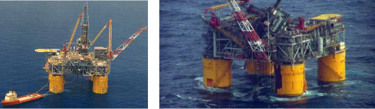
Navigating Mother Nature's Challenges: Ensuring Safety in Offshore Drilling Operations | Helmerich and Payne
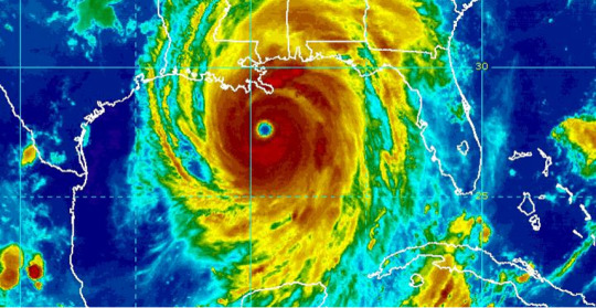
ANTICIPATING THE INEVITABLE: WEATHER PREPAREDNESS
Drilling rigs are exposed to the elements, and the unique environment of an offshore drilling rig in the Gulf of Mexico has its own unique potential issues. The inevitability of adverse weather underscores the necessity for meticulous preparation. It’s not a matter of “if” but rather “when” such challenges will arise. Hurricanes loom as one of the most dangerous threats to an offshore rig. As hurricane season approaches, meticulous planning commences well in advance under the banner of Actively C.A.R.E. Rigorous preparation and frequent review of procedures ensures swift responses when hurricanes threaten operations.
VIGILANCE IN FORECASTING: MONITORING AND ACTION
A network of workgroups diligently monitors weather patterns year-round, comprised of contractors, operators, and third-party service providers. The first trigger for action begins when a tropical weather system may be over 1000 miles away. Once a weather system is identified, and it is projected to enter the Gulf of Mexico, rig leadership initiates action plans and procedures. Rig leadership follows protocols, ensuring the proper equipment is available to secure the well, removing nonessential personnel and equipment off location, and developing a full evacuation plan if needed. If the system is identified as a threat to the rig, the hurricane evacuation procedure is initiated. Once the threat ends, the teams continue to work their plans which include preparations to transport crews back to the rigs in order to assess the damage and perform any necessary repairs or remediation.
BEYOND HURRICANES:MITIGATING DIVERSE WEATHER RISKS
While hurricanes command significant attention, other oceanic weather phenomena create additional challenges. From lightning strikes to unusual sea states and water spouts, each demands a tailored response. Thunderstorms are electronically monitored on the platform for lightning strikes, because offshore drilling rig masts and crane booms are normally the tallest structure for many miles. Once a threatening system is within three miles of the rig, crane operations are suspended, and rig crews are prepared to stage in safe zones. Wind speed indicators are used by crane operators to monitor wind speed so that they can suspend operations any time the wind speed reaches 35 mph or greater.
Read out the full HSE News from here: https://bit.ly/3J20CB9 or you can also download the PDF of the article from here: https://bit.ly/4aA2o8o. Contact us to know more about our HSE News: https://bit.ly/452JYdl.
#rigcontractoroilandgas#drillingtechnology#helmerichandpayne#drillingautomation#drillingrigcontractoroilandgas
0 notes
Text
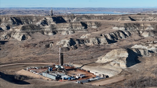
Drilling in Tornado Alley: A firsthand account of a rig manager who had to take cover | Helmerich and Payne
While my children can sometimes be compared to small tornados, that’s not what I mean. Tony’s account of his experience demonstrates the importance of staying aware and alert at all times, with the safety of those you’re responsible for as your highest calling. The demands of the job are high – around the clock, for the both of us, there’s a job to do. Drilling rigs are inherently exposed to the elements.
Equipment must be designed to withstand some of the most severe environmental conditions, with drilling taking place in nearly all climates around the globe. Desert sands in the Middle East provide constant sandblasting effect and rigs must be outfitted with larger tires to move efficiently from one location to the next. Feet of snow can accumulate in the northernmost rig sites. Maybe you’ve seen North Sea TikTok? As the Shale Boom has progressed in the United States, unconventional long lateral wells are drilled in areas that encounter severe thunderstorms and tornadoes on a regular basis.
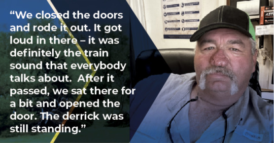
As a native Oklahoman, I’ve grown up knowing how to “take cover” during a tornado warning, but most Oklahomans have never actually experienced being in the path of a tornado. Crews on drilling rigs must expect tornadoes as a very real possibility, and Tony Maynard, H&P employee of 17 years and Rig Manager of over a decade, can give a firsthand account of a tornado hitting his drilling rig. “I definitely won’t forget April 19, 2023. We had just started running our production string casing, there was roughly 21,000 feet of pipe in there.
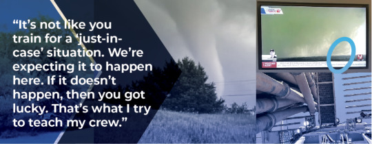
We had 2,500 feet of casing in the hole. Between my superintendent calling in to just tell me to watch over the weather, and my safety people were doing it as well. We knew something bad was coming our way. I was watching it too when I realized it was coming in our direction.” Drilling sites are host to a high activity operation. Depending on the stage of the well, the operator and drilling contractor, there are a number of various third-party service companies coming and going on location in order to complete their task. “The superintendent was trying to get to us, but it was pretty bad all around there – roadblocks everywhere.
If we resumed operations and something were to happen to somebody out there, we wouldn’t be able to get any help to them. We shut down operations that night and waited until the next morning to assess the situation.” The next day, Engineering arrived, drones in tow. “We had damage to the derrick board. We ended up laying down casing after the engineers came out with drones. It all had to be inspected before we could even move the blocks. And before the crew could even go up, we had a drone inspect pens and make sure nothing was torn loose.” After a thorough inspection, it was determined that the damage incurred to the derrick board was severe enough to warrant a change out.
Once the tasks of laying down casing and drill pipe were completed, the derrick was then lowered and replaced. The crew was cleared to resume drilling ahead. “Yeah, that was April 19. Then on May 11, we had another one, right across the highway from us. You could chunk a rock at it.” Drilling in remote locations – whether in the middle of the ocean, the middle of a rainforest, or the middle of rural Oklahoma – brings its own set of issues when inclement weather takes place. Multiple methods of monitoring exist in the event that systems are unavailable.
The Starlink satellite system on all H&P rigs, storm radios, high tech rig phones, and even a basic antenna for local channels all ensure accurate and up to date weather information is available. Read out the full HSE News from here: https://bit.ly/3vsbhSH or you can also download the article from here: https://bit.ly/3U1Pzhu. Contact us to know more about our HSE News: https://bit.ly/452JYdl.
#rigcontractoroilandgas#drillingtechnology#helmerichandpayne#drillingautomation#drillingrigcontractoroilandgas
0 notes
Text
Helmerich & Payne Drilling Performance 2023 | Drilling Contractor H&P

We have had a great year (and great 103 years). Check out some of the incredible achievements we have had. One of the most impressive ones might be the gross savings we have provided our operators. 🤔 Curious how Helmerich & Payne could help you achieve better drilling outcomes? 𝗘𝘅𝗽𝗹𝗼𝗿𝗲 𝗺𝗼𝗿𝗲 𝗵𝗲𝗿𝗲: https://www.helmerichpayne.com/our-ap...📖 Read more about our 100+ year history here: https://www.helmerichpayne.com/aboutCheck out other H&P Drilling technologies here: • H&P Technologies 🏆 🏆 See why we have won the 𝗘𝗻𝗲𝗿𝗴𝘆𝗣𝗼𝗶𝗻𝘁𝗲 𝗥𝗲𝘀𝗲𝗮𝗿𝗰𝗵 𝗖𝘂𝘀𝘁𝗼𝗺𝗲𝗿 𝗦𝗮𝘁𝗶𝘀𝗳𝗮𝗰𝘁𝗶𝗼𝗻 𝗔𝘄𝗮𝗿𝗱 for the past 15 years straight: https://www.helmerichpayne.com/our-ap...@energypointresearch5171 award winners listed here: https://www.energypointresearch.com/s...
#rigcontractoroilandgas#drillingtechnology#helmerichandpayne#drillingautomation#drillingrigcontractoroilandgas#drillingrigcontractor
0 notes
Text
To What Extent Can the Notion of an Effective Length Be Reliable to Assess the BHA Lateral Behavior? | Helmerich & Payne
Many models in the industry use the notion of an effective length to make predictions about the bottom hole assembly (BHA), whether for its directional behavior or its lateral vibration tendency. A given criteria is chosen to cut the drill string at a certain distance from the bit and use only that part for the computations. In this paper, this cutting distance is referred to as the effective length.
Though computationally efficient, and thus providing fast real-time predictions, there is no consensus on what criteria should be chosen, nor a "bulletproof recipe" on how to compute that length. Miscalculating this effective length, especially for vibration mitigation purposes, can lead to suboptimal rotation speed selection, potentially causing failure. To address this challenge, different choices of effective length computations are compared in terms of BHA yield rate prediction (build/drop and turn rate).
Past a given distance from the bit, the computed side force and tilt at the bit are nearly identical, meaning that any element very far from the bit is negligible in the static calculation. However, studying lateral vibrations is more complex especially at low inclinations or in horizontal wells with high weight on bit (WOB) where the drill string can move more freely with snaking and whirling motions. A nonlinear time-domain model is utilized to evaluate the propagation of lateral vibrations up the string.
A sensitivity analysis was then conducted on several BHA types and lengths, considering different boundary conditions in vertical and horizontal wells. Directional models are found to be reasonably unsensitive to the choice of the effective length because they are based on steady-state computations, but the same cannot be stated for dynamics.
This study developed a more robust approach to estimate properly the effective length for lateral vibrations, an essential for BHA resonance. Read out the full tech paper here: https://www.helmerichpayne.com/resources/technical-publications/to-what-extent-can-the-notion-of-an-effective-length-be-reliable-to-assess-the-bha-lateral-behavior or you can also download the pdf from here: https://www.helmerichpayne.com/media/technical-publications/SPE-217755-MS.pdf. Contact us to know more: https://www.helmerichpayne.com/contact.
#rigcontractoroilandgas#drillingtechnology#helmerichandpayne#drillingautomation#drillingrigcontractoroilandgas
0 notes
Text
My H&P Journey: Juan | Drilling Contractor H&P
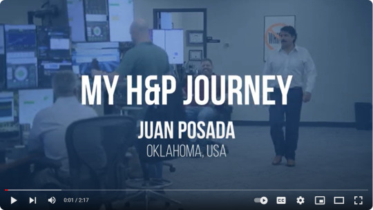
Juan's journey to and throughout Helmerich and Payne is one of passion for creating solutions for abstract problems. Juan studied at the University of Tulsa as a petroleum engineer.
Because of the connections he made in college, he walked into a job interview for an engineering tech position and knew the interviewer as an old college friend. After a short interview, he was offered the job on his drive home.
His work-life balance while at H&P has allowed him to measure his time at H&P by years and how many children he has had. Watch more H&P Journey videos here: • What's it like being an intern at H&P...
#rigcontractoroilandgas#drillingtechnology#helmerichandpayne#drillingautomation#drillingrigcontractoroilandgas
0 notes
Text
Improving surface oscillation tools performance using time-domain dynamics and torque and drag models | Helmerich & Payne
Overcoming friction in sliding mode represents a challenging task when drilling an unconventional well with a long lateral section. Among the possible ways to reduce these frictional forces is to use a surface oscillation tool (SOT). By alternating the rotation at surface between the forward and reverse directions, apart of the friction forces is transferred from the axial to tangential direction.
Hence, a better transmission of the weight to the drill bit and increased rate of penetration can be achieved. To take full advantage of this tool, an accurate and fast modeling of the influence of its oscillation characteristics is necessary. The SOT is operated at surface by changing its rotation speed and number of wraps in forward and reverse directions. If these characteristics are underestimated, the torsional oscillations are quickly stopped by the friction moments, and the rate of penetration is not increased enough.
However, if they are over estimated, the torsional oscillations can reach the bent motor, and destabilize the tool face orientation (TFO). In this paper, a full time-domain dynamics model and a simplified model coupled with a stiff-string torque and drag model are used to identity the influence length of the SOT, and hence provide an opportunity to optimize its operating parameters. Full and simplified models are compared to each other to ensure their validity.
Namely, the effect of the drillstring-wellbore contact distribution is showed to have a substantial impact on the SOT performance. Consequently, it was proved that optimal SOT characteristics Off-Bottom are generally not enough to overcome the friction when drilling. In addition, the torque and drag model is applied to a real case study of an unconventional well with surface and downhole data. Read out the full tech paper here: https://www.helmerichpayne.com/resources/technical-publications/improving-surface-oscillation-tools-performance-using-time-domain-dynamics-and-torque-and-drag-models or you can also download it's pdf from here: https://www.helmerichpayne.com/media/technical-publications/Improving-Surface-Oscillation-Tools-Performance-Using-Time-Domain-Dynamics-and-Torque-and-Drag-Models.pdf. Contact us to know more: https://www.helmerichpayne.com/contact.
#rigcontractoroilandgas#drillingtechnology#helmerichandpayne#drillingautomation#drillingrigcontractoroilandgas#drillingrigcontractor
0 notes
Text
Fatigue tracking for mud motors and mwds in unconventional wells | Helmerich & Payne
As the industry continues to drill increasingly complex wells, the demand put on drilling equipment has increased and will continue to increase. Preventive maintenance often falls to the wayside in favor of keeping the same equipment operational for longer until a failure occurs, which can be very costly and potentially catastrophic to the equipment provider. Fatigue tracking makes it possible to predict failures ahead of time and prevent such incidents.
However, the most commonly used fatigue tracking methods are based only on rotating hours and do not take the bending stress into account. Electronic drilling recorders (EDR)coupled with bottom hole assembly (BHA) models allow for better estimation of the fatigue performance by calculating the actual bending stress along each piece of equipment, such as the mud motor or measurement while drilling (MWD) tool, leading to a more reliable fatigue tracking method.
A case study of fatigue on a common motor and MWD over the drilling life of a well provides valuable information on how to monitor and react to different fatigue scenarios. By using an advanced stiff string model to calculate stress distribution along the motor or MWD coupled with standard fatigue prediction models, valuable information can be learned about the motor and MWD conditions.
One case that will be examined involves a typical well trajectory such as those drilled in the US land market today which involve a high dogleg curve to reach a target formation, with dog leg severity (DLS)locally reaching 18 (deg/100') generating high bending stress and thus fatigue. The consequence on fatigue life can be dramatic through the BHA for even just one exceptionally high dogleg.
By using the continuous surveys taken by an MWD tool, to account for the actual tortuosity of the well, the potential fatigue becomes even more significant. Read out the full tech paper here: https://www.helmerichpayne.com/resources/technical-publications/fatigue-tracking-for-mud-motors-and-mwds-in-unconventional-wells or you can also download the pdf from here: https://www.helmerichpayne.com/media/technical-publications/Fatigue-Tracking-for-Mud-Motors-and-MWDs-in-Unconventional-Wells.pdf. Contact us to know more: https://www.helmerichpayne.com/contact.
#rigcontractoroilandgas#drillingtechnology#helmerichandpayne#drillingautomation#drillingrigcontractoroilandgas
0 notes
Last Seen Blogs

designouruniverse
Design Our Universe

falkenbergbidstrup
The Life of Holman 170

the-algid
dog/wolf John CEO

tisuayp
Nipples

zenialifebook-blog
Zenia-MyLifeBooks