#and that was just for desoldering the old switches
Text
replacing the switches in my keyboard was a huge success. it sounds so good. it sounds almost creamy. god...,
#i eat bees.#i was hunched over. all muscles tensed. squinting.#for four. hours.#and that was just for desoldering the old switches#the new ones was a breeze i did that all in like 20 mins#but oh my god im stiff. im sore. my hands have cuts and also sores#but so worth it.#and it was fun too!!!!
8 notes
·
View notes
Text
Dynaco Repair Post No. 7
"And you may say to yourself, my god! What have I done?!?!?"
January 17, 2024
Wednesday Evening
I knew this was going to be fraught with all manner of hell before I started. I mean, just remove and replace the most intricate piece in the whole damn preamp. Using a used part. That needs...things.
Make no mistake, I knew what I was in for here, I'm just warning y'all, who have made it through all these many chapters in the saga.
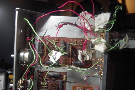
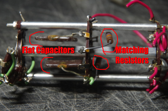
I decided to leave the wires I'd soldered onto the new jacks and clip the wires at the switch. The replacement has all the wires (thank goodness) but it is missing the two flat capacitors and resistors that are soldered in between the second and third wafers in the switch.
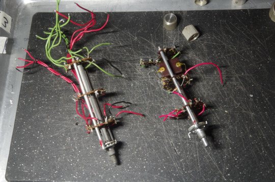
Replacement on the left, mine on the right. I have to desolder those four components still on mine and put them on the the replacement.
And with my little wire truss taken off and the third wafer wires gone, you can see exactly where it broke.
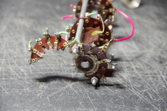
So that is where it all sits tonight. It was kinda nerve-wracking trying to decide whether to desolder or clip and I settled on clipping at the old switch, which was probably the best idea.
An interesting observation: while clipping the wires, there were several that went right down to the phono board below, and were just slipped into little tubes and soldered in place. Except for one. It just pulled right out of its little tube.
This had to be this way before I did all the work before, so it had no bearing on how it worked. Just interesting to me that it worked in spite of not being done correctly the first time.
11 notes
·
View notes
Text
Finally bit the bullet, ordered a new mouse. Been a proud user of the logitech g700 for about 12 years, bestest mouse ever, tho for the last 4 or 5 years I've been struggling with double clicking. If they still produced this model I would absolutely buy another one, but alas decided to get g502 x lightspeed.
I would've just changed the switches, I even got new ones, but after changing out double clicking switches on my other old logitech mouse (identical to m525, but it is an older model, think it had a different model name), I'm terrified to try that on my g700. The m525, or the older brother that I have, is super simple, unscrew the board and desolder the 3 pin switches and replace, simple right... fuck me that was a pain the ass. Just couldn't get all of the old solder off, barely could get the old ones out and barely could squeeze the new ones in, however, in the end, it was a success.
G700 has a mainboard and then an upper sister board connected with 8 or 10 soldered through hole pins. The sister board has to be desoldered and disconnected to have access to the switches. I have 0% chance to do that, don't know what equipment I'm missing, and am not inclined to experiment. Was thinking of asking someone else do the soldering, but I don't know anyone, and hadn't bothered to find anyone.
I had been browsing mice for a good few years since g700's discontinuation, but not one mouse has looked like a good replacement. I like the size(big), shape(good for my clawish grip), weight(heavy, important), and the many completely programmable buttons(even more important). Even looked at g502 and g502 x before and thought they were not good replacements, but looked today again, did some maths, and concluded:
1. Loss of 1 extra button. Technically g700 has 4 next to thumb and 3 next to index finger, while g502 x has 3 and 2 respectively, BUT, one of the index finger buttons I've only ever used as a battery level indicator, which has never really been all that necessary, so I won't count the loss of that button a loss.
2. Loss of 49 grams. That's from 151 to 102. That sucks, but with gaming mice these days, that's the heaviest I'll get. Shame the g502 x doesn't have counterweight/balast system like other logitech mice have had.
3. Possibly gained a more ergonomic mouse. The g700's buttons are fine but some are not the easiest to get to. It looks like, and I hope that all the g502 x's buttons are easy to get to.
Uuuh the hell am I doing here. 3.25 am, maybe better to go to bed.
1 note
·
View note
Photo
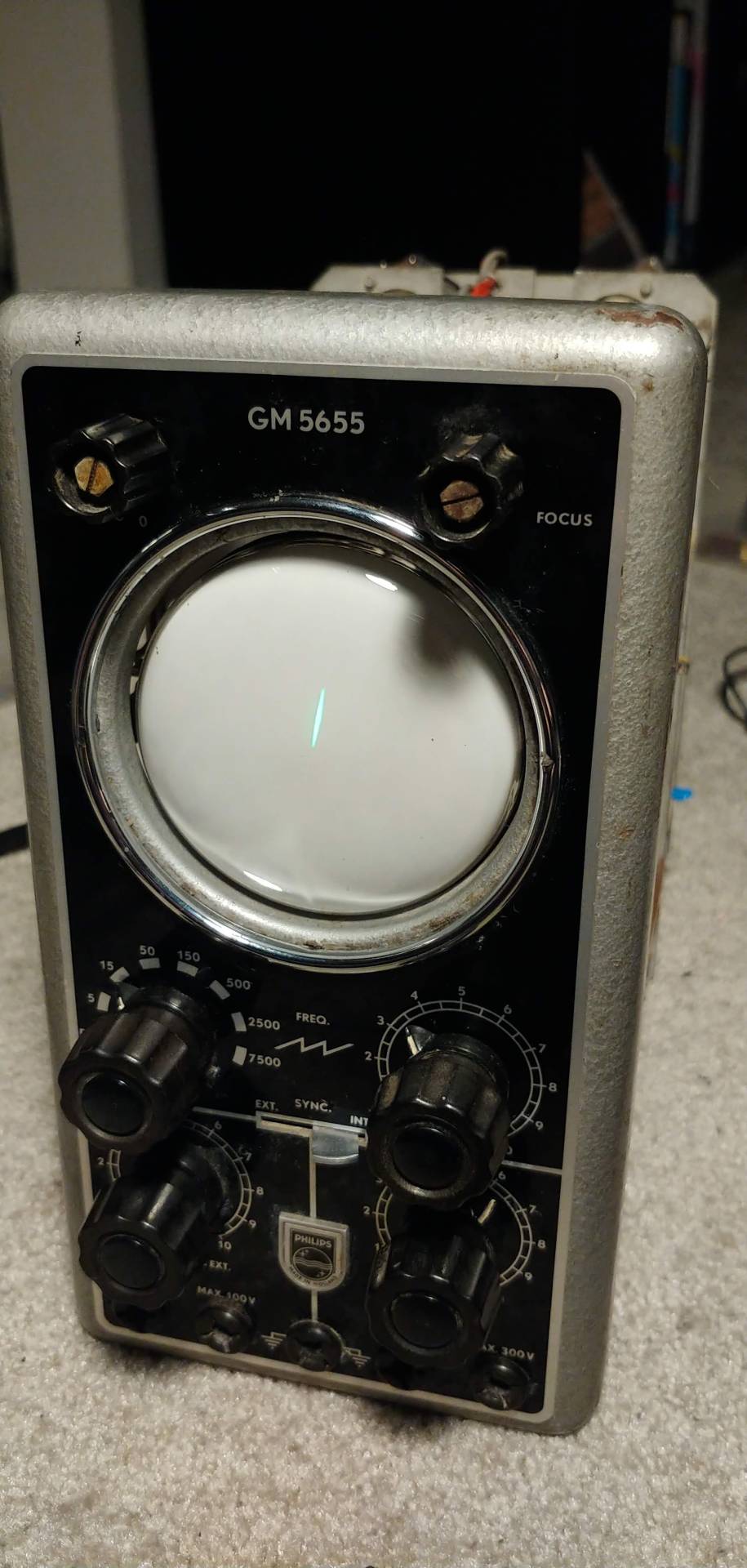
scope restore part 3
so it is time for some serious troubleshooting. now personally I’ve never actually encountered a cold solder joint. but if there was going to be one it would probably be inside of this old ass barn scope. so after consulting the fully dutch manual and reseating the tubes for good measure. I got a schematic for it’s power supply and was able to test for voltages from the transformer. and they would come alive and go dead seemingly at random. ٩(ఠ益ఠ)۶
it was strange because it would either have 120v on the primary side when it was on or it would have basically 0v on the primary side when it was on yet draw 0 current??? (@_@) I’m writing a complaint letter to georg ohm as we speak
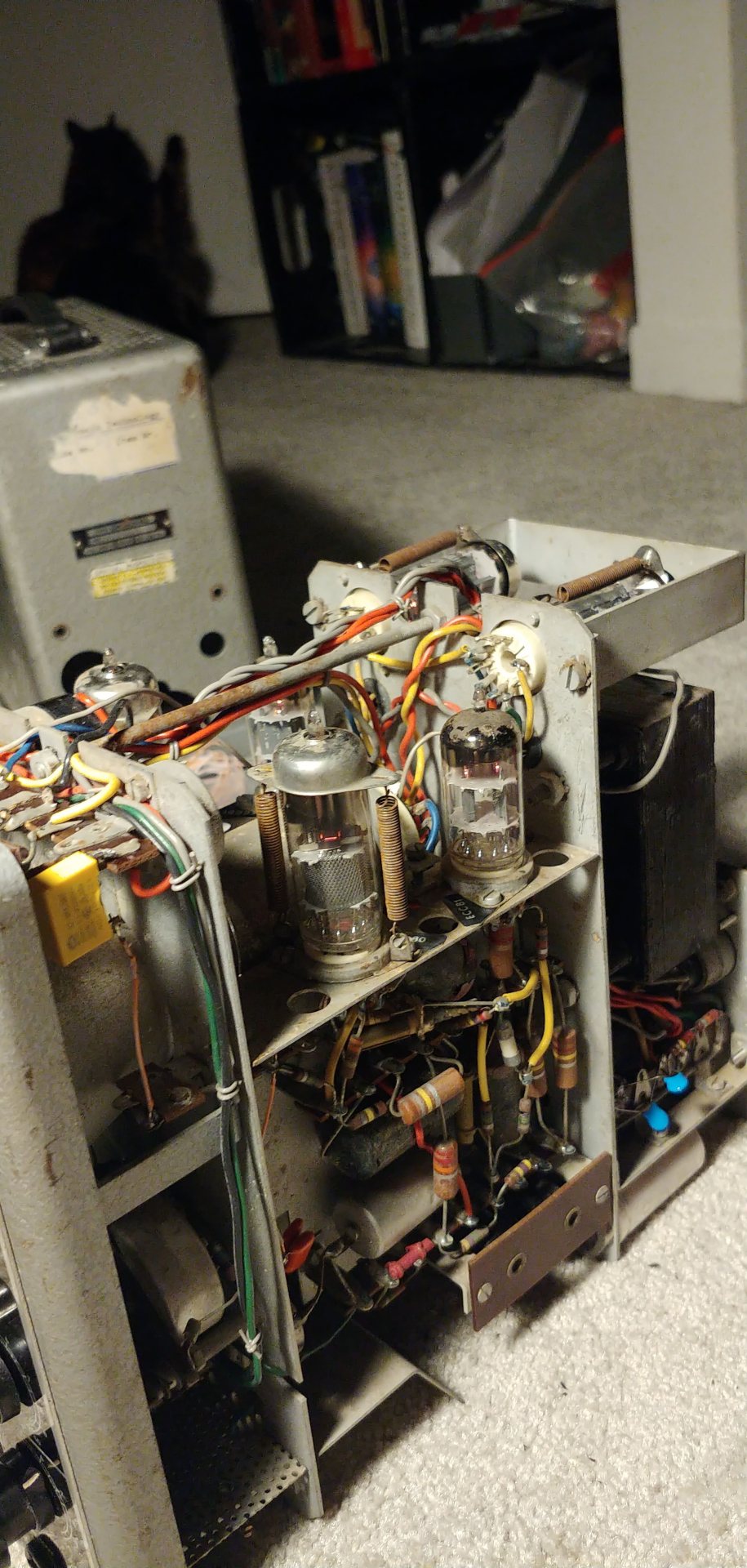
after a few hours of desoldering and resoldering everything connected to the primary side of the transformer (inculding a very neat mains voltage selector switch with 110,125,145,200,220,245 volt options; making this scope pretty much able to be powered on from any socket in the world. (yet still only having a dutch manual available)) I dicided to say fuck it and just remove the whole damn transformer to test if there was some sort of short/ open winding.
it tested good which was a relief and so to celebrate I got rid of a lot of unnessary bs in the circuit like the mains voltage selector, a weird 3 pin input connector at the back and these totally broken testing switches that can be seen in the bottom of the second pic. yippe ! less failure points. (* ^ ω ^)
I resoldered and mounted the transformer back into the machine and gave it a test and it WORKS NOW !! (not like fully actually working but like it turns on and gives trace)
so things are good. it turns on and seems to react to a change in voltage at it’s inputs appropriatelyish. no proper horizontal movement tho, but that only gives me more fun things to fix. couldn’t be that easy right?
so step 4 is going to be replacing all of it’s many black beauty capacitors ( https://w140.com/tekwiki/wiki/Bumble_Bee_capacitors ) that have surely gone bad by now along with some drifty carbon composite resistor enamies.
(งಠ_ಠ)ง
so now I just have to wait for the replacements I ordered.
1 note
·
View note
Text
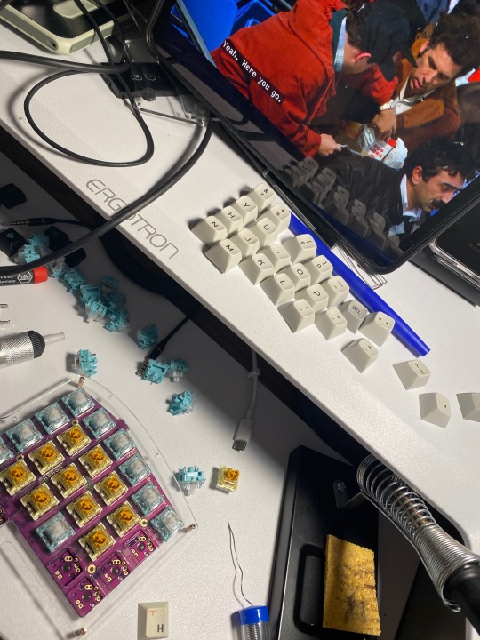
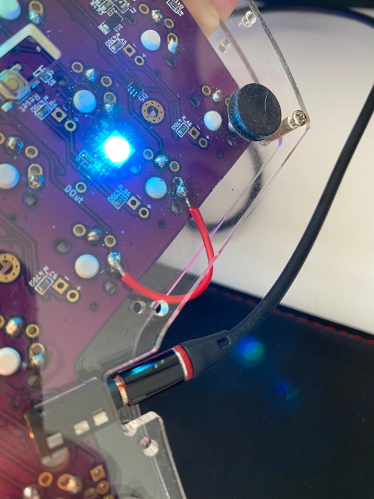
I spent this weekend desoldering bunch of keyboard switches and soldering new ones in, because I didn’t like the old ones I had for a couple of years. but I fucked up and destroyed the copper sockets that a couple of keys didn’t work afterwards….. so I just messed around with a wire to see if I can bridge them to make it somehow work (and it somehow worked). Terrible soldering job because the soldering iron was a shitty Amazon buy and the tip of the soldering iron started bending under the heat and breaking and oxidizing etc 💀 and I didn’t have any flux on hand but I wanted to finish it before Monday so I can have a keyboard for work. It’s all working now!! Ready for clickyclacky. I also got a new bass and I’m actually kind of excited, bc the one I had was a travelers/practice bass that sounded awful in recording. The new one is a full scale jazz bass which will be really heavy and big for my teeny tiny twinky body but I mean. I think I’ll make it work. It’s coming on Wednesday and I’m excited to try to make a cover video or something just so I can see my progress and form! The options for my first video are Head over Heels, Supermassive Black Hole, or going super easy and doing Lovesong since I'll have to get used to the new instrument? anyways.


4 notes
·
View notes
Text
XD84 build - what is this madness
I’m building up a new XD84 pro from KPRepublic. This is my 3rd build with this style of PCB, the 87% keyboard, but the first time building a pro model.
From a previous build, I had an unused aluminum case in black just sitting here, so I figured I’d build something around what I had... kind of like if you have 4 tires sitting in your yard, and one day you say to yourself “I might as well fill up the space between those tires with the rest of a car”, then start buying car parts from China. You know the story, it’s happened a million times.
So of course I want only the finest for my beautiful anodized case
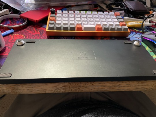

There she is, all nice and pretty like a pony.
I start plugging these lovely SP-Star weirdo clone MX keyswitches into the PCB & plate. Testing fitment, making sure everything is all squished in before soldering in the switches.
Things are coming along quite nicely.
EXCEPT..
The PCB will not fit in the case.
See the Pro model of the XD84 now comes with this:

“Oh cool” you might say, “It’s an expansion port of some kind! Looks standard as hell. It’s probably to add an LED strip or something that would be useless in this case. Let’s see what it is”.
Now I am dumb, yes. This much can be proven scientifically. But I am not a bad googleman. I can Bing with the best of them. You can Duck Duck Go fuck yourself if you think otherwise. I could not, for the life of me, figure out what the fuck this huge connector was for.
There’s loads of awesome info out there for the older versions of this board, like this right here:

This new board is perfectly different than the old one. It’s much prettier for one, but there’s less expandability (probably a good thing as that seems pretty unnecessary given this form factor) and a way better onboard controller.
If you look on the XD84 Pro product page, there’s plenty of pictures and a decent English writeup of what’s what.
Here’s what the specifications are for the board
Parameter Specification 1\75% kit 2\Can support MX Switch 3\Compatible with KLE custom key 4\Supports TKG-TOOLS offline and TKG online flash 5\Standard ICSP interface 6\REVB and REVQE compatible expansion port 7\Support Underglow RGB PCB 8\Support Type C USB port
OK. Neato. What?
WTF is REVE and REVQE?
WTF is a standard ICSP interface?
Maybe this bulky POS connector is one of those things. Research time.
Start looking up REVQE (because why would I use the obviously inferior REVE???) - that leads me here.
Not a lot of help at first, then some helpful dude is like “
Pins F4-F7 land on expansion pin-out at the top of the board (cluster labeled P5). From top to bottom, they are F7,4,6,5.” Oh here, check out the schematics of this other, similar board
Now if you’re a dumb dumb like yours truly, you see that and your eyes go cross. Plus, that looks nothing like this 4 pin connector in any way, that’s lots of lines, this should be around 4 lines. More likely than not, this stupid port is not REVE or REVQE. Onward!
Let’s look up ICSP:
ICSP stands for In Circuit Serial Programming, which represents one of the several methods available for programming Arduino boards. Ordinarily, an Arduino bootloader program is used to program an Arduino board, but if the bootloader is missing or damaged, ICSP can be used instead. ICSP can be used to restore a missing or damaged bootloader.
A typical Arduino ICSP header has six pins, arranged 2x3. The article Connecting the Programmer: In-Circuit Serial Programming (ICSP) at Sparkfun describes some of the functions of ICSP pins, which include MISO, MOSI, SCK, V+, Ground, and Reset.
Each ICSP pin usually is cross-connected to another Arduino pin with the same name or function. For example, MISO on an Uno or Nano's ICSP header is connected to MISO / digital pin 12; MOSI on the ISCP header is connected to MOSI / digital pin 11; and so forth. Note, MISO, MOSI, and SCK pins taken together make up most of an SPI interface.
Several Arduinos, including the Uno, have two ICSP headers. One of them is for use with the ATmega328 (or similar), and the other for use with the ATmega16U2 (or similar) chip that implements USB. When present, this allows reprogramming the USB chip.
Yeah pretty sure this ain’t it either, and if it is, I shouldn’t need it. So. What the gosh darn shit is this thing?
I go back to the XD84 page because at this point I have no idea what’s going on. I’d been searching around for hours, getting nowhere and getting there really slowly. Somewhere on the page there’s a “link” to a video
How to assemble XD84 Pro ? pls click this link: https://www.youtube.com/watch?v=BKw4b7gEG80
Unclickable link, right. Good job web design homie.
I start watching the video, it’s actually pretty funny since it seems like this guy is either left handed, filming with his left hand while trying to use his right hand to clumsily grab stuff.. or he’s got his phone in mirror mode or something. Lots of table slapping trying to find the thing
Hold up, what the FUCK is that thing
That has the same goddamn connector... what the shit??

OH YOU MOTHER FUCKERS
So, guess what time it is?

SNIP SNIP BITCH
So now the bottom of the board is so fresh and so clean clean


The ol’ full disclosure “I tried to desolder it first” shot

GLAMOROUS
This shit’s going to be so dope looking when it’s done.
Almost ready to start soldering, just waiting on flat-top 3mm warm white LEDs for the backlighting. In the meantime, why wouldn’t I make the most obnoxious CAPSLOCK indicator??

5MM bright white LED will let me know that Cruise Control For Cool is in full effect.
#mechanical keyboard#mechkeys#led#frustration#kprepublic#novelkeys#sp-star#mx#homemade#red#pretty#glorious china#Samantha Brown: Passport to China#Samantha Brown#reve#revqe#snip snip#soldering#solder#lead fumes#health
2 notes
·
View notes
Text
Moronavirus!
Just to be totally up front and honest with y’all, I gotta let you know that personally, I’m rooting for the coronavirus at this point. As a pal posted on Facebutt: “China virus will not kill anywhere near enough people to raise the average IQ of the planet.” I have to say I agree. Best of luck to you and yours, on with the synthing!
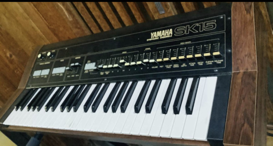
Impulse buy that I pretty much immediately regretted. I have a soft spot for string machines. I had a Korg Lambda a few years back. Probably shouldn’t have sold it. But I did. Saw the SK-15 for $100 on the auction and thought yeah why not? Not the worst sound by far, but given I’ll hardly use the organ section, and the synth section is almost as bare-bones as you can get, well, yeah it’s already sold. Seriously I think I had it a grand total of two and a half weeks if that. It’s in great shape cosmetically, and came with the flight case, but some of the buttons were stubborn so I thought I’d desolder them, disassemble and repair whatever needed repairing. Here’s what one of the ginormous button assemblies looks like:
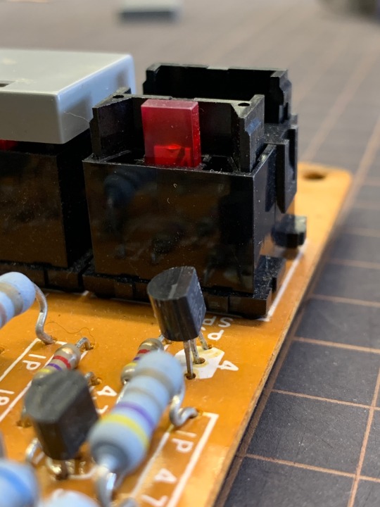
Popped the business end off. And here’s one desoldered and discombobulated:
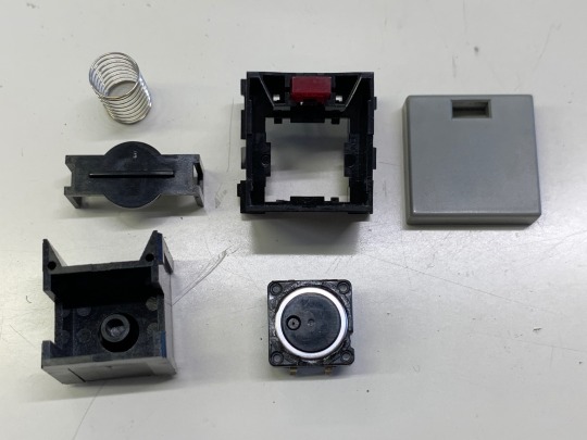
Standard tact switch right there bottom row, center. It was a quick job to swap the old ones out, but anyone out there wanting to do this needs to be sure to replace the switches with ALPS SKHCBFA010 as opposed to the better, sealed Omron switches because of this:
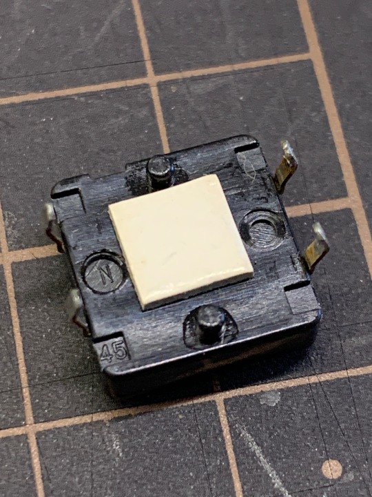
Look carefully and closely at the corners. At lower left you can see a 45 there yeah? Those indentations are what wee clips on the underside of the big button housing snap into. Omron tact switches don’t have those. Also, that white cardboard square plastered on serves a purpose, it ensures that the switch stays a certain height off the PCB. So you’ll need to carefully pry those off and stick ‘em on the replacement switches (double sided tape did the trick). After they were all done, two were still acting up. As far as I could tell, it was due to the way the LED sorta snaps into place, almost like the snap gets in the way and doesn’t let the moving part of the switch housing to return to its original position. If I had more time (and ambition) I would’ve probably given the inner part a light sanding on the sides that contact the outer housing, and that may have opened up just enough leeway for the switch to move more freely. But I didn’t. I did replace the dirty felt-like strips that surround the sliders, and where the hinged front panel rests on the keys, and that looks nice. Kind of a lot of elbow grease and TLC for something that spent so little time here. I do like to see things off in better shape than when I got them though.
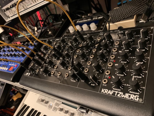
It’s MFB Mofuggin’ Mania!! Feast your bezoomny grahzny glazzies on that horrorshow chellovek, O droogs. KRAFTZWERG!!! The Power Dwarf!!! Basically it’s the guttiwuts of the Synth 2 (which you can see there too), but with no memory, no sequencer, no “keyboard,” instead you get patch points. This thing sounds fat as fuck. Patching stuff on the KRAFTZWERG is like if you fed the Synth 2 a big batch of LSD. Madness!! I’m seriously thinking of selling the Polivoks now. Yes, it’s THAT good. The Polivoks filter is a whole different kind of insanity, but otherwise it’s a pretty sterile but very good sounding synth (only one LFO, no PWM, no bender or mod wheel) though the looping envelope bit is very appealing. Hmmmmm. Anyway, KRAFTZWERG!!!!!!!

And the latest in the MFB bunch is the Tänzbar Lite. Basically an MFB-522 with (drum roll please) maybe a few more sounds, less noise, a set of LFOs, and PARAMETER LOCKS!!! Yeah I totally wasn’t expecting that. I have an MFB-503 and that one saves the sound settings per pattern, which is a fantastic feature, but the Tänzbar Lite takes it a step further with parameter locks. The big drawback with it is the learning curve, and havibg to get used to some very counter-intuitive button press combos (you have to hold shift+play to start and stop the onboard sequencer....why it’s like this is anybody’s guess). Anyhow I’ve been using a Drumbrute Impact for a little while now, and while I LOVE the sequencer and I do like the general sound, I find the bass drum a bit flabby when the decay is cranked, and the snare almost totally lacks any punch at all (remedied with individual output and processing but that requires extra braincells, cables, and devices, and I just wanna get shit done already). And of course, no parameter locks, and no saving of sound settings per pattern (or at all really, it’s in perpetual “Manual” mode). So yeah, see ya later Drumbrute Impact. MFB for me. I’ve got one more special guest showing up this weekend, so keep a lookout for a new post soon. Until then, be well, but don’t be afraid to die. Worse things can happen.
#fucktrump#satan#diy synth repair#aaaargh#mfb tanzbar lite#yamaha sk15#mfb kraftzwerg#madness#gogocoronavirus
2 notes
·
View notes
Text
Logitech's new mechanical keyboard lets you swap switches with ease
Programmers, power users and gamers can be picky about their keyboards. Not only do some prefer old school microswitch keys, but they also want to get specific about what types of microswitches are under their keycaps. Logitech G's latest device, the PRO X Mechanical Gaming Keyboard, will let you swap between three varieties of switches, providing assorted types of feedback and key travel, from "linear" to "clicky." The keyboard is aimed at pro gamers, but amateurs may also be drawn to the high-end compact design, precision and obligatory RGB lighting.
The PRO X uses GX switches, which come in several varieties and are color-coded by feel. GX brown switches are described as "tactile" and give clear but quiet feedback upon a button press. Red "linear" switches are closer to standard keyboards and have a smooth keystroke. Blue switches elicit that loud, "clicky" noise and feel that typists from bygone eras look back on with either nostalgia or disdain.
Logitech G will sell packs of 92 replacement GX switches for the PRO X for $50 each when the keyboard goes on sale later this month, which will be enough to replace each switch on the device. The real draw here is that the switches are hot-swappable; most keyboards' switches are soldered to the circuit board. Making a swap on the PRO X should take less than an hour, as opposed to the days of work it could take to desolder and resolder every switch on a standard keyboard. For those who just want a PRO X without the swappable functionality, Logitech G will also offer a version of the keyboard outfitted with permanent blue switches.
Customizable keyboards aren't exactly new. Drop (formerly called MassDrop) offers hot-swappable keyboards that can also be customized further with colored keycaps and other accessories. Logitech G's entry into the market signals a mainstream demand for these types of keyboards, and the brand's size and long-standing supply chain mean lower prices than boutique shops can offer. The PRO X Mechanical Gaming Keyboard will retail at $149.99 and the PRO Mechanical Gaming Keyboard (without the swappable microswitches) will cost $129.99.
Source: Logitech
- Repost from: engadget Post
0 notes
Text
How to clean retro gaming systems
New Post has been published on https://nexcraft.co/how-to-clean-retro-gaming-systems/
How to clean retro gaming systems
Ditch the 3D graphics. Haven’t you heard? Retro is back. (Lorenzo Herrera via Unsplash/)
Collecting retro video game systems can be dirty work. As time goes on, there are fewer consoles in circulation, so if you want to score good deals, you’ve got to be a lot less picky about condition. Fortunately, there’s still plenty of great stuff out there in relatively good shape—you’ve just got to be willing to scrape years worth of dust from grandma’s attic off them.
Cleaning video game consoles takes some delicacy, and you want to make sure you use the right tools and solvents, lest you damage labels and plastic. Yellowing from sunlight exposure can be a significant issue as well, and you can pick up many systems on the cheap if you know how to take care of that corn chip-colored coating.
So if you’re looking to breathe new life into your TurboGrafx-16, look no further than this list detailing the dos and don’ts of cleaning vintage tech. You can use them for modern electronics, too, but we’ll be placing particular emphasis on the situations you’ll run into while cleaning retro consoles or computers.
What you’ll need:
The most important part of cleaning retro systems is making sure you have the right tools for the job. These machines contain a plethora of materials, but the primary one is plastic—usually either acrylonitrile butadiene styrene (ABS) or polybutylene terephthalate (PBT). That means you’ll need a non-corrosive solvent and very soft cleaning tools. Fortunately, the best stuff to clean old electronics is also relatively cheap.
My recommended cleaning kit is:
<a href=”https://amzn.to/2KqGJX6″>Paper towels</a>
<a href=”https://amzn.to/2YV5n65″>Cotton swabs</a>
<a href=”https://amzn.to/2YV5AGp”>Cotton balls</a>
<a href=”https://amzn.to/2KpBEOx”>Soft toothbrushes</a>
<a href=”https://amzn.to/2GWy7W6″>99% isopropyl alcohol</a>
The five items above will cost you about $20 and allow you to tackle any dirty console you find. If you use everything carefully, you won’t have to worry about scratching or warping any plastic you encounter.
Prepare yourself and your machine
Dive into your parent’s basement and you’ll probably find your old Nintendo. Don’t expect it to look like this, though. (Franck V. via Unsplash/)
We’re going to assume you’ve got a real dirty system—something that has sat in an attic, barn, or shed for years, is covered in bug poop, dust, and has an old funk to it that makes it smell like Dracula’s castle.
Before you start a thorough cleaning, you should disassemble your console. Depending on which system you’re working on, this will take up most of the time you were planning to invest in the project.
First, make sure you familiarize yourself with the disassembly and assembly process, which will vary in difficulty depending on the model, and may require specific tools. Do yourself a favor and run a quick Google search to see exactly how hard the job will be. Some systems, like the Super Nintendo or Nintendo 64, are relatively easy to take apart, but you’ll need to purchase a special screwdriver to do so. Others, like the Sega CDX, are held together by standard Phillips-head screws, but their complex construction makes them a huge pain to take apart and put back together.
If you couldn’t convince your parents to get you a GameBoy Clear, this is your chance to get up-close and personal with your console’s guts. (Dimitri Houtteman via Pixabay/)
I’ve never run into a system that didn’t have in-depth disassembly instructions posted somewhere—you can check enthusiast forums, Reddit, or use the Wayback Machine—but it’s still good advice not to bite off more than you can chew. Many a retro enthusiast has taken apart a console only to break a vital, hard-to-replace part during the process.
With that said, for any restoration or cleaning process, you’ll first want to take a good, hard look at everything as you open it all up—you don’t want to have to take it apart again. Take a snapshot if you need to, because you may need to reference it later.
Once you’ve stripped your console down, you’ll need to sort its parts into groups according to how you’re going to clean them. For parts such as regular plastic casing, you can just use a toothbrush and alcohol with impunity. With others, such as circuit boards, wires, and plastic with labels, you’ll want to be much more careful. When I’m cleaning a console, I like to sort the parts by how much attention they need. This way, I can get all the harder-to-clean stuff—with lots of nooks and crevices—done first so it has a chance to dry while I’m doing the easy bits.
Take a good, hard look at everything
The reason you disassembled your (presumably) super-dirty console was so you could take care of the dirt both inside and out, but also to inspect the guts of your system for damage.
The biggest threat to a retro system’s life—especially if it was manufactured before 2000—is bad capacitors. These little cylinders of death are the bane of anyone who seriously collects retro consoles, and catching bad ones early can help save your machine.
Most console capacitors are filled with electrolytic gel. Unfortunately, a lot of pre-fifth generation consoles (made before 2000) were built with exceptionally poor-quality capacitors to reduce manufacturing costs, and 30 years down the road, many have started leaking. The electrolytic gel inside is corrosive, which affects consoles in two ways. Obviously, a failed capacitor will prevent the system from working properly, but the leaked gel will also eat through the circuit board and cause permanent damage.
The easiest way to tell if a capacitor is bad is if you notice a yellowish-brown residue on top of it. That means it’s leaking and you need to remove it as soon as possible. Sometimes they’ll burst directly onto the board, so make sure you examine the area around any capacitors for a poopy brown crust, which is a telltale sign you’re in for some trouble. They won’t spontaneously burst while you’re working on the console, but you’ll want to look out for those that have gone through the process in the past—no explosions to be wary of here, thankfully.
Yes, your NES probably looks good on the outside, but gamer gunk gets everywhere! (RobinLe via Pixabay/)
But before capacitors burst, they start to swell. That means you can have failed or failing capacitors with no leakage. Finding a swollen capacitor is harder than finding one that’s leaking, because the difference is often subtle. Your best bet is to mark for replacement any capacitor that doesn’t have a perfectly flat top.
There are capacitor replacement kits available on eBay or specialized websites for even the most obscure systems, and if you can’t manage to find one, you can purchase replacement capacitors individually on Amazon for reasonably cheap. This should cost about $15 to $20 for more obscure systems, and much less for more commonly available units.
The consoles most heavily affected by capacitor issues are early CD-based systems. In particular, the Sega CD (Model 1, especially), Sega CDX (but not the JVC X’Eye, for some reason), and TurboDuo (known as the PC Engine Duo in Japan) are the most notorious offenders. Sega Game Gears and Pioneer LaserActive PAC-S1s and N1s also have lousy reputations when it comes to capacitors. If you have a rare machine, like the LaserActive PAC units, just change the capacitors, whatever they look like. You don’t want to take the chance that a printed circuit board (PCB) on a machine with a production run of less than 50,000 is destroyed by something as weak as bum capacitors.
Another thing to look for during your inspection is rust. PCB components won’t oxidize under normal circumstances, but if the system has been submerged in water or stored in a particularly humid location, you may be looking at some rust damage. Most of the time, it affects non-essential components like PCB shields and switches, so depending on the level of damage, you might be able to run the console without the rusted part or just clean it the best you can and live with the rust.
Clean the circuit board
Circuit boards are delicate. Treat them with some special TLC. (studdedmagpie via Pixabay/)
Now you’re ready to clean your console. I usually start with the circuit boards since they are the most fragile part and will need more time to dry than the case. Less is more when cleaning these pieces. When scrubbing your board, you want to use as little pressure as possible. Just dip your soft toothbrush in a light amount of alcohol and gently dust the entire surface of the PCB. Under most circumstances, even on a console with a filthy exterior, the motherboard isn’t going to be caked in anything. A good dust-off should be more than adequate.
On the off-chance that your board is caked in dirt, dust, snot or whatever, you might want to think about desoldering some of the more frail components, such as through-hole capacitors and resistors (the ones that go through holes on the board, not the ones mounted on its surface), so you can scrub the board more freely. If the board is absolutely filthy, you might be better off, in the long run, replacing these parts, since they frequently cause issues if they’re damaged. You may be able to find these at hardware stores like Lowe’s, but most of them will be special-order only.
Clean the CD drive
If your console contains a CD drive, you’re going to want to clean it as well. A good rule of thumb here is to not actually touch anything unless you have to. Be especially aware of the adjustment potentiometers, which usually look like cross-shaped dials. Unless you know what you’re doing, don’t mess with these at all. Definitely take a picture of these before you get to cleaning, just in case you nudge one by accident.
These little dials control the alignment, voltage, trim, and other aspects of your laser. If these are set to the wrong values, the best case is your laser won’t work well. In the worst case, the incorrect adjustments will bust the laser and you’ll need to find a new laser assembly.
After a deep clean, the only thing you need to do with a CD drive during a routine touch-up is dab a bit of alcohol on a cotton swab and gently wash the lens. That’s it—your laser assembly will be good to go.
Remember that round, bubble-like thing you used to blow at when your Earthworm Jim game wasn’t running? Yeah, don’t touch it. (Hello I’m Nik via Unsplash/)
Cleaning the console case
Cleaning the case is the easiest part of this whole process. Most of the time, you can just go wild here. Get your paper towels out, pour a good amount of alcohol onto them, and give all the parts of the shell a good wipe-down, inside and out. This might take a few passes on particularly foul systems, but it shouldn’t take too long to get most of the enclosure looking pretty good.
The tricky part of cleaning a system is getting into all the cracks and crevices. There will be residue and gamer gunk left in the nooks and crannies even after a good scrubbing with paper towels. When this issue presents itself, the toothbrush will likely be your best recourse. Just dunk it in alcohol and start scrubbing wherever there’s dirt left. Take it easy, though. If you scrub too hard, the bristles will bunch up and the brush will lose its effectiveness.
If your case happens to have adhesive labels, you’ll want to avoid scrubbing those areas on your general passes. Instead, use a cotton swab and only clean the very edge surface of each decal. The main thing you want to avoid is getting under the edge. As long as the sticker remains flat, you’ll be fine.
Take it easy on stickers and adhesives—you don’t want to scrub Diddy and Daisy Kong off of your cartridge. (Kevin Roden via Pixabay/)
After you’ve done your pass with the toothbrush, look for any remaining dirt. For tiny areas, you may need to use a cotton swab. But at this point, you should be pretty much good to go. Still, even after everything looks clean and you’ve set your toothbrush aside, give the whole case one more wipe-down with paper towels in case you stirred up any gunk.
By now, your console should be looking near-new. There’s not a lot you can do about any existing scratches or dents, but it should, at the very least, look refreshed. If there was any yellowing, the thorough cleaning should have helped some, especially if the discoloration was from cigarette tar. If it’s from sunlight, though, you may want to leave the console disassembled—now that it’s clean, it’s a great time to put it through the Retr0bright process which can reverse damage from ultraviolet light.
If you’re satisfied with the results of your cleaning, reassemble your console. The cool thing is: as long as you keep a clean house, you should only have to dust your system and wipe it down with a paper towel every once in a while. You shouldn’t need to do a full deep clean ever again, so you’re free to just enjoy your console and game away.
Written By Brittany Vincent
0 notes
Text
Wokka-wokka – All the tone, but none of the suck, the Vox Wah True Bypass mod!In my initial foray into the world of wah, I bought a Jim Dunlop Crybaby from my local ma and pa guitar shop. I had a horrible drive pedal, the DOD Grunge pedal, and the wah. I was going for Hendrix, SRV, Satriani… Yes, I had sounds in my head I was trying to match. Sadly, none, and I mean NONE of my setting on the crybaby came even close to where I wanted to be. About five years later, I tried a Vox V847 wah and fell in love! This was the true tone I had been looking for. It had a simple sweep, a minimalistic build, and the Vox V847 model really is built for interchangablility and tinkering.
A side note: I have owned the Deluxe Clyde Fulltone wah as well. All of the bells and whistles are on this pedal, but the Vox just nails the tone that I need in an absolutely economical and well built package.
I would go so far as to say that if you are entering the world of pedal modding, start with a Vox V847 pedal. Swap out some parts and get your soldering skills up to par. All of the mode one will do to this pedal are certainly felt, and heard. Perhaps the most important mod, however is the Vox wah True Bypass mod.
Vox Wah Guts – after
Materials needed:
Vox V847 wah pedal – find on Reverb.com
24 gauge wire – http://amzn.to/2jFDLh2
3pdt Effect Pedal Switch – http://amzn.to/2jsxCp3
Tools needed:
Wire Strippers – http://amzn.to/2jg7Kj3
Soldering Iron Kit – http://amzn.to/2ilH3tM
Screwdriver – http://amzn.to/2jNrM5f
Small Adjustable Wrench – http://amzn.to/2ilAKpY
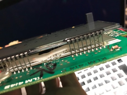
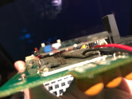
You can see by the pictures that the old switch in place already has three wires attached to it. We will reattach all three of these wires to the poles of the 3pdt switch.
Here are the steps in order.
Desolder wires to SPDT (stock switch), remove it, and Install new 3PDT with the connection tabs running horizontally to the length of the wah pedal.
Remove circuit board with screwdriver
Cut Brown wire where it meets PCB Quick Disconnect Harness, reinstall circuit board.
Desolder other end of brown wire from the input jack.
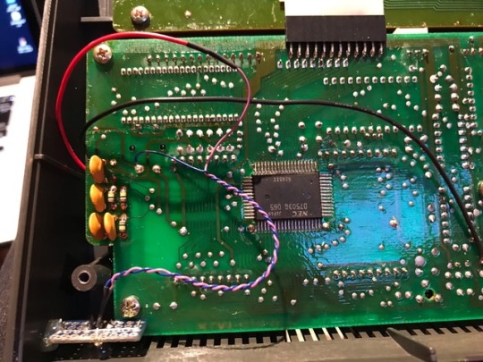
Cut new length of wire and solder to where the brown wire was on the input jack. I use a purple wire in my build. Route this wire along side of the other three (green, blue, and white) to the new switch.
Solder wires in these locations of the switch
Green (from Harness) to the top left hand corner of the switch.
Blue (from Pot) to the top right hand corner of the switch.
White to the the terminal righ hand center row.
The new wire (mine is purple) from your input jack to the left center row of the switch.
Adda jumper wire between the lower left and lower right terminals of the switch.
You are done!!!
This mod bypasses the circuitry of your wah pedal when it is “off”. The tone suck has been bypassed, making your signal a bit more “true” :-)
Tone heaven! Enjoy!
Pictures below!
#gallery-0-4 { margin: auto; } #gallery-0-4 .gallery-item { float: left; margin-top: 10px; text-align: center; width: 25%; } #gallery-0-4 img { border: 2px solid #cfcfcf; } #gallery-0-4 .gallery-caption { margin-left: 0; } /* see gallery_shortcode() in wp-includes/media.php */
The Vox V847
Remove switch
Desolder and remove switch
remove circuit board
snip off Brown wire at harness
Vox Wah guts After
Note purple wire running around the pot
close up of switch
purple wire
Another closeup
Vox Wah True Bypass mod Wokka-wokka - All the tone, but none of the suck, the Vox Wah True Bypass mod!
0 notes
Text
KPR-77 Backlight LED Mod
Right. Happy birthday to me. 11/24. Fortyfucking-eight years old. Better have the fire dept standing by when the candles on the cake get lit, if my goofy fucking family even bothered to get me a cake that is. Anyway...
Yeah so the lamps that Korg put in the KPR-77 for lighting the LCD are... well... cool in an 80s dashboard lights kinda way. But the switch is momentary so they’re only on for as long as you hold the button down. I guess because they appear to be actual incandescent lamps, generate heat when on, and have a limited life span, Korg went with the momentary switch. I may have said all this before in my previous post but anyway, I thought it would be nice to have LEDs that are the same brightness or a bit brighter, that could be switched on and off independently of the factory lamps. So, parts shopping I went.
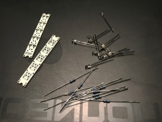
First attempt. I found these neat LED strip PCBs and thought hey that would work. Solder everything together only to find that they won’t fit under the LCD. Fuck. Fine, I took a diamond file to the epoxy lenses of the LEDs, and filed off about 1.5mm. I also fitted little condom-looking diffuser hats onto the LEDs but in the end I was worried that the spacing was gonna be too tight, and the light not diffused as much as I wanted. Back to the drawing board. And back to Osaka for parts for the second day in a row. Aaaaaaaaargh.
I was thinking I’d have to use SMD LEDs and resistors or it was gonna be a huge pain in the ass to fit the little LED PCBs in under the LCD. Ok then, so be it. I was also wondering whether I should install a pot so I could have full time control over the brightness of the LEDs, OR install an on-off-on switch, and run a 1k and a 500ohm resistor to the two “on” lugs of the switch, and have the option to choose between two levels of brightness. Hmmmmm. I went with the latter after thinking about the size of available pots and not really wanting a big fat knob jutting out in some odd spot. So, after buying all the parts I needed I came back home and started construction.
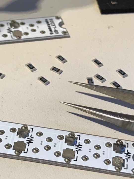
Goddam SMD resistors are fucking small. But I’ve gotten used to soldering SMD stuff so it was an easy job. Three minutes and both boards were done. Next, the LEDs.
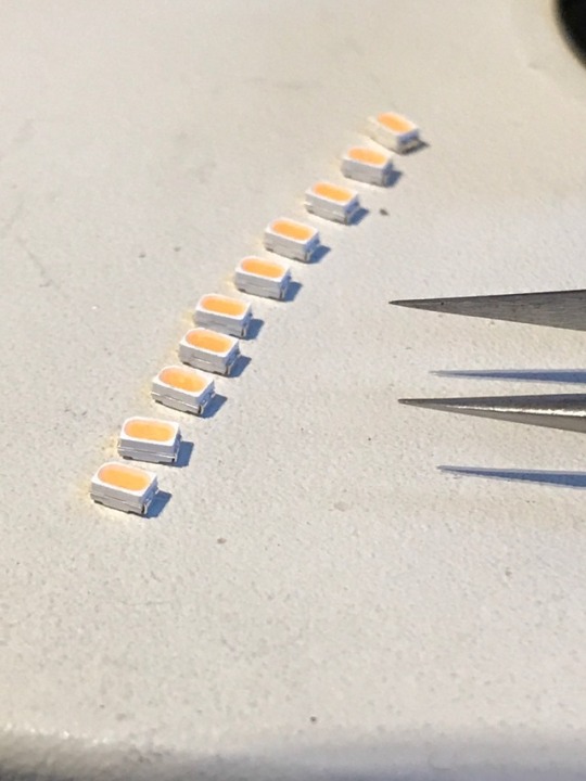
Jeeeeezus these fucking things are tiny too. And polarized. Know how to tell the polarity? Me neither! Internets here I come!
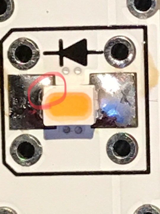
See that wee fucking notch I circled there? That indicates the cathode, or minus end. Yay. Anyway it was easy to find out and easy to solder, easier than the resistors just because the LEDs were a smidge bigger. Next, test time!
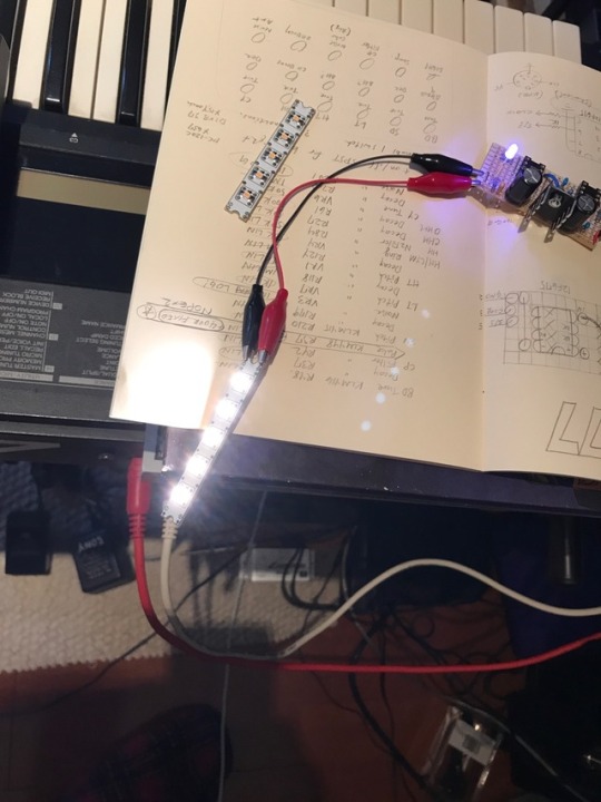
Goddam that’s bright. That’s at 5v too. The KPR uses 6v. Well, let’s slap a 1k resistor in front of the works. Did that and it was a helluva lot dimmer. Anyway, the 1k and 500ohm resistors on the switch should work out fine. Not done yet!
I put a layer of two strips of tracing paper on top of the LEDs as a diffuser. Then electrical taped the bottom sides, and put strong double sided tape on top of that. Finagled the pair of boards in under the LCD, pushed down in strategic spots to get the double sided tape to take hold, then gave a few careful, sparing squirts of hot glue here and there just to be sure. Here’s the view from the top.
Side view. You can see a set of ceramic capacitors there at the bottom right. They were in the way so I desoldered them and then resoldered them in from the underside. Same for three wee resistors that were there too. Yeah ok it ain’t looking half bad. Now I had to go about wiring up the switch and everything else.
The switch required drilling a 4mm hole in the case. I wanted to mount the switch on the side, and drilled a hole, but then discovered the screw post there at lower left kept the switch assembly from going down to where the hole was. Aaaaaargh. Covered the hole with tape, on the inside and outside of the case. Then went with the next best place, on the rear panel, a bit above and to the outside from the DC jack. No problems there. Soldered the wiring, put everything back together and then crossed my fingers and turned it on.
That’s full brightness. Not bad.
And that’s half brightness. Yeah cool.
Not as warm as the original lamps (which still work, but there’s a limit as to how many photos you can put in one post, laaaaaaaaaame) but not blindingly fucking high-beam HID headlight bright either. Not bad. Not bad at all.
1 note
·
View note
Text
Triple Double DW
On a whim, I picked up a DW-6000 a while ago, for quite cheap. It was fun, and reminded me of its successor, the DW-8000, but with fewer waveforms to choose from, no velocity or aftertouch, and chorus but no delay. It wasn’t too long before I was looking back fondly on the days when I had an 8000... so I started looking through auction listings and I saw one in super good condition, but listed as “junk, no power cord so it’s not been tested.” What the hell, might as well. Double and a bit what I paid for the 6000. I have a power cord. So the 8000 arrived, I plugged it in, turned the power on and got absolutely nothing. No click, no buzz, no smoke, nothing. (Sigh). Opened it up, found the fuse had blown. Picked up a pack of ten fuses, popped one in, and POW! Blew the fuse. Ok let’s check the power supply, specifically the regulators and caps. Nothing visibly wrong. Hmmm. Ah what the fuck it’s an old synth, parts used in the power supply board are cheap, let’s just rebuild the power supply. New regulators, new caps, half an hour later and it was time to test it out. I unplugged all the power connectors to the main and other PCBs, just in case. Everything on the power supply tested out fine. Connect everything back up again, and... well... the relay clicks, but the program, parameter and value LEDs don’t light up. The only indication the thing is getting power is from the arp speed LED, which lights up and stays lit. Great, a troubleshooting nightmare just waiting to be dealt with. Aaaargh. I don’t have the time or patience right now for this. Wonder if I can google anything useful about these symptoms. Found a few posts on forums made by people with the exact same issue but nobody posted anything that was even close to “I fixed it and this was what was wrong!” All the posts end with “the arp LED comes on and stays on but otherwise the synth is frozen.” So I have no idea. What a let down.
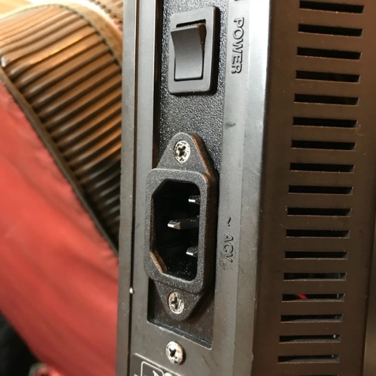
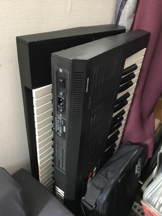
Killing time online last week, I saw two more 8000s listed. One in good shape, the other in so-so shape and with a power-cable-soldered-directly-inside “mod” so I thought hmmm. Ended up bidding on and winning the latter, which arrived today.
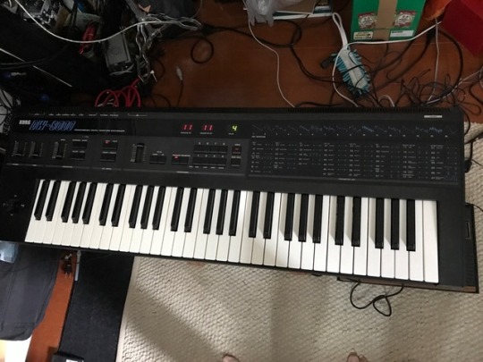
With fingers crossed and a few prayers said to the evil spirits of the universe, I plugged it in and turned it on. It works. Edited a program to check the functionality of the buttons, the filter, amp and delay and all are fine. Surprisingly, it is not noisy at all. Velocity and aftertouch are fine too. Yay! But look at this:
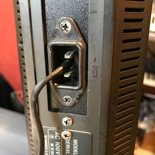
WHO DOES THIS KIND OF SHIT?!
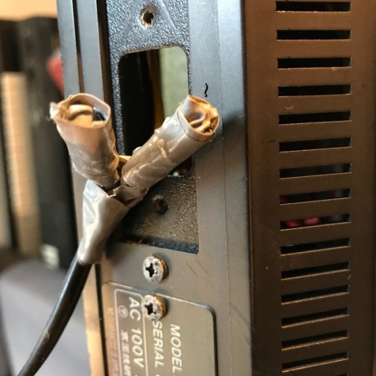
ARE YOU FUCKING KIDDING ME?!
In the end, I clipped the wires, desoldered the leads to the switch (ended up pulling the backside off the switch inadvertently, fucking hell, now I know what the innards of that particular power switch look like and how to correctly reassemble one), removed that little panel by unscrewing it and finagling it very carefully so it would come out (all angles and gentle coaxing). Then I took a file to the socket area of the little panel, as new sockets are just a tad too big to fit as is. Ten minutes of sweating and the socket went in smoothly. Solder everything back up, grab a standard power cable, plug in and test. Everything working fine. Screw the panel back on, screw the socket in, and that’s that.
Now the only thing left is to figure out what to do with these guys...
1 note
·
View note
Last Seen Blogs

anayvch28
Ana Vargas

beardedbugger
Untitled

maxindiahealthcare
Maxindiahealthcare

prongsiepotter
MOONY LOVE CLUB

marshalllange52
The Journaling of Perkins 601