#Toradex Blog
Text
First Steps Developing Embedded Applications using Heterogeneous Multicore Processors – Compiling and Deploying Applications on the Cortex-M core is easy!
Every day, new heterogeneous multicore processors/System on Chips (SoCs) are launched in the market. The incorporation of microcontrollers and peripheral cores on SoCs is becoming a very common practice, look at the latest releases of NXP®: i.MX 6SoloX, i.MX 7 and the upcoming i.MX 8 (recently announced to be in the Toradex Apalis family). Looks to me like something that happened in the past when the ADC (Analog Digital Converter) started to be integrated as peripheral functions on the microcontrollers, having the microcontroller core in an application processor, is solving several issues related to real-time control on Linux-based solutions.
Today, Toradex has two established System on Modules (SoMs)/Computer on Modules (CoMs) based on the Multicore Heterogeneous architecture, namely the Colibri iMX7 and the Colibri VF61. Two more modules will be released soon, the Colibri iMX6ULL and the Apalis iMX8 thereby ensuring the scalability of customers across its pin-compatible families.
The introduction of a new technology always raises a lot of questions and you might be asking yourself whether there would be a lot of implementation. The purpose of this article is to show a quick and clear starting path to the development of an application with the heterogeneous multicore approach. Here we will cover the basic procedure to set up the environment and start the development, creating a ping pong application showing how to establish communication between cores and finally, show in the last example a practical use case where the microcontroller core reads an ADC data over SPI and send the information to the microprocessor core running the Linux operating system.
This is a series of articles aiming to demystify the development of embedded systems using Heterogeneous Multicore Processing architecture powered SoCs. Through a practical approach and presentation of several demos, this will provide you a quick start to your development.
Hardware
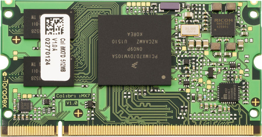
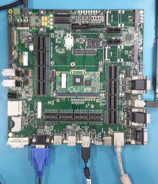
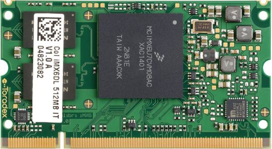
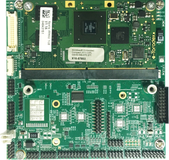
For this article, the Toradex dual core Colibri iMX7 System on Module was selected: this module is equipped with a NXP i.MX7 SoC, a dual-core ARM Cortex-A7 core plus an ARM Cortex-M4 core, with CPU clock of 1GHz for the A7 and 200MHz for the M4, plus 512MB of flash memory and 512MB of RAM. The module is presented in the image below:
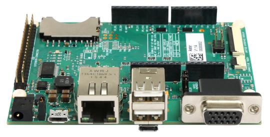
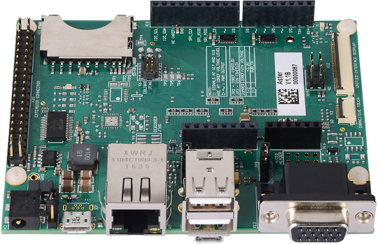
The Aster has been chosen as the carrier board. It is a new release from Toradex that makes life easier for those who are developing a new project. This carrier board has the standard Arduino shields connector, allowing developers to use the various Arduino shields prototyping modules available off-the-shelf in the market to reduce their design time.
In addition to the Arduino shield, a connector with the same Raspberry Pi pinout is also available, allowing the use of modules developed for this hardware, facilitating not only the prototyping of new designs, but also the transition from proofs-of-concept to scalable and industrial quality and life-time guaranteed hardware like Toradex.
Setting up the environment
The examples presented in this article were developed on a Linux host machine. All the code for Cortex-M is based on Makefile and Cmake. To compile the examples, just install a few packages and correctly configure the toolchain.
We recommend the linaro toolchain version 4.9 2015 Q3. After downloading the tar package from the link here, extract it as below:
tar xjf ~/Downloads/gcc-arm-none-eabi-4_9-2015q3-20150921-linux.tar.bz2
Since the toolchain generates 32-bit binaries, install the 32-bit version of libc and libncurse. For Ubuntu, the commands are:
sudo dpkg --add-architecture i386 sudo apt-get update sudo apt-get install libc6:i386 libncurses5:i386
Now it is time to test the toolchain:
~/gcc-arm-none-eabi-4_9-2015q3/bin/arm-none-eabi-gcc --version arm-none-eabi-gcc (GNU Tools for ARM Embedded Processors) 4.9.3 20150529 (release) [ARM/embedded-4_9-branch revision 227977] Copyright (C) 2014 Free Software Foundation, Inc. This is free software; see the source for copying conditions. There is NO warranty; not even for MERCHANTABILITY or FITNESS FOR A PARTICULAR PURPOSE.
Finally, install cmake and make:
sudo apt-get install make cmake
Downloading the example
We prepared a couple of examples to be downloaded and easily tested, they include basic "Hello, World!" to inter-core communications. Start downloading the source code repository:
$ git clone -b colibri-imx7-m4-freertos-v8 git://git.toradex.com/freertos-toradex.git freertos-colibri-imx7/ $ cd freertos-colibri-imx7/
All the source codes that we will use as reference are in this folder. The folder structure is already done to support the Colibri iMX7 and also the FreeRTOS. Inside this structure the folder that we will most use is the folder containing all the examples:
[raul@localhost freertos-colibri-imx7]$ tree -L 2 examples/imx7_colibri_m4/ examples/imx7_colibri_m4/ ├── board.c ├── board.h ├── clock_freq.c ├── clock_freq.h ├── demo_apps │ ├── blinking_imx_demo │ ├── hello_world │ ├── hello_world_ddr │ ├── hello_world_ocram │ ├── low_power_imx7d │ ├── rpmsg │ └── sema4_demo ├── driver_examples │ ├── adc_imx7d │ ├── ecspi │ ├── flexcan │ ├── gpio_imx │ ├── gpt │ ├── i2c_imx │ ├── uart_imx │ └── wdog_imx ├── gpio_pins.c ├── gpio_pins.h ├── pin_mux.c └── pin_mux.h 17 directories, 8 files [raul@localhost freertos-colibri-imx7]$
Setting up the hardware
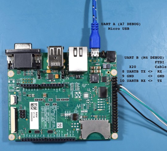
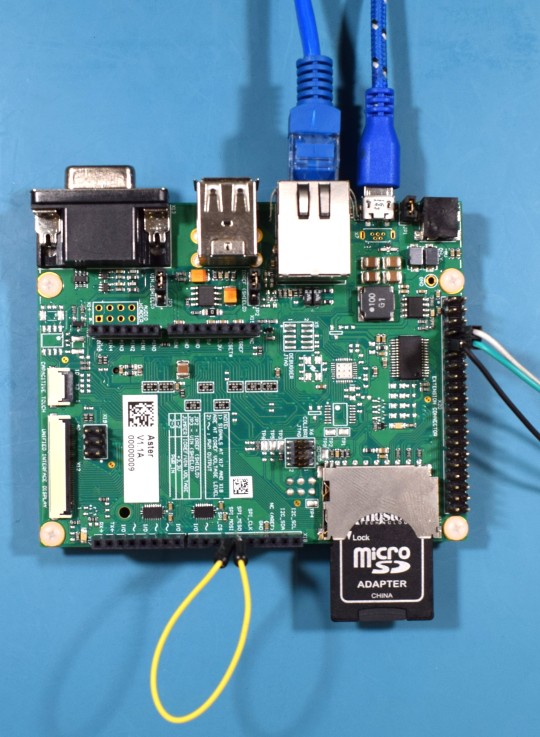
In this article, we are not covering how to debug on Cortex-M, so we will use a UART to get the messages printed by the firmware. It is very important to understand how to set up the environment to get a productive development set. Since the Cortex-M and the Cortex-A cores share interfaces, it is necessary to know that the messages printed on the UART B will be printed by the Cortex-M firmware and the messages in the UART A will be printed by Cortex-A (U-boot and Linux).
Therefore, we will use two different cables for UART A and UART B. In the case of UART A, it already has an FTDI chip on the Aster carrier board, and the connection is made by connecting it to the USB X4 connector. This connector is being used to power on the board as well as access the UART A, so when connecting it to the computer the device /dev/ttyUSBX should be recognized automatically.
For UART B, the TX and RX pins of the Colibri iMX7 are connected in the X20 expansion header. Since there is no FTDI chip or Serial RS-232 converter for this interface, you need to use a cable popularly known as the FTDI cable. Connect the RX, TX, and ground pins of the FTDI cable to the connector X20 pins 8, 10, and 9 respectively.
Finally, the cables must to be connected like the picture below:
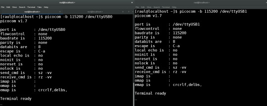
Now that the cables are properly connected, open two terminals on Linux with “picocom” and open the serial ports:
Terminal 1:
[raul@localhost ~]$ picocom -b 115200 /dev/ttyUSB0
Terminal 2:
[raul@localhost ~]$ picocom -b 115200 /dev/ttyUSB1
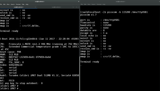
You may have something like the following image:
Compiling the first example
To compile the first example, go to SPI example directory:
[raul@localhost freertos-colibri-imx7]$ cd examples/imx7_colibri_m4/driver_examples/ecspi/ecspi_interrupt/master/ [raul@localhost master]$ ls armgcc hardware_init.c main.c
Note that all of the examples have the files main.c, hardware_init.c and the folder armgcc. We will not explain the source code now, just go to the directory, export the toolchain path that we downloaded and compile the example:
[raul@localhost armgcc]$ cd .. [raul@localhost master]$ cd armgcc/ [raul@localhost armgcc]$ export ARMGCC_DIR=~/gcc-arm-none-eabi-4_9-2015q3/ [raul@localhost armgcc]$ ./build_all.sh -- TOOLCHAIN_DIR: /home/raul/gcc-arm-none-eabi-4_9-2015q3/ -- BUILD_TYPE: Debug -- TOOLCHAIN_DIR: /home/raul/gcc-arm-none-eabi-4_9-2015q3/ -- BUILD_TYPE: Debug -- Could not determine Eclipse version, assuming at least 3.6 (Helios). Adjust CMAKE_ECLIPSE_VERSION if this is wrong. -- The ASM compiler identification is GNU -- Found assembler: /home/raul/gcc-arm-none-eabi-4_9-2015q3//bin/arm-none-eabi-gcc -- Configuring done -- Generating done -- Build files have been written to: /home/raul/freertos-colibri-imx7/examples/imx7_colibri_m4/driver_examples/ecspi/ecspi_interrupt/master/armgcc Scanning dependencies of target ecspi_interrupt_master_example [ 5%] Building C object CMakeFiles/ecspi_interrupt_master_example.dir/home/raul/freertos-colibri-imx7/platform/utilities/src/debug_console_imx.c.obj ... ... ... [ 94%] Building C object CMakeFiles/ecspi_interrupt_master_example.dir/home/raul/freertos-colibri-imx7/platform/drivers/src/uart_imx.c.obj [100%] Linking C executable debug/ecspi_interrupt_master_example.elf [100%] Built target ecspi_interrupt_master_example -- TOOLCHAIN_DIR: /home/raul/gcc-arm-none-eabi-4_9-2015q3/ -- BUILD_TYPE: Release -- Eclipse version is set to 3.6 (Helios). Adjust CMAKE_ECLIPSE_VERSION if this is wrong. -- Configuring done -- Generating done CMake Warning: Manually-specified variables were not used by the project: CMAKE_TOOLCHAIN_FILE -- Build files have been written to: /home/raul/freertos-colibri-imx7/examples/imx7_colibri_m4/driver_examples/ecspi/ecspi_interrupt/master/armgcc [ 5%] Building ASM object CMakeFiles/ecspi_interrupt_master_example.dir/home/raul/freertos-colibri-imx7/platform/devices/MCIMX7D/startup/gcc/startup_MCIMX7D_M4.S.obj ... ... ... [ 94%] Building C object CMakeFiles/ecspi_interrupt_master_example.dir/home/raul/freertos-colibri-imx7/platform/drivers/src/uart_imx.c.obj [100%] Linking C executable release/ecspi_interrupt_master_example.elf [100%] Built target ecspi_interrupt_master_example [raul@localhost armgcc]$ The binaries are located in the "release" directory. [raul@localhost armgcc]$ cd release/ [raul@localhost release]$ ls ecspi_interrupt_master_example.bin ecspi_interrupt_master_example.hex ecspi_interrupt_master_example.elf ecspi_interrupt_master_example.map [raul@localhost release]$
In our case, the file ".bin" is the most important. Let´s use U-boot to load it on the Cortex-M4.
Executing the firmware
To execute the firmware, it is necessary that U-boot load the binaries and run the file on the Cortex-M. It is possible to do this in different ways. My suggestion is to use a SD card (FAT32) or network. We will show the instructions to do it both ways. On one hand, keep in mind that while using the network the development occurs in a dynamic way, since it is not necessary to plug and to unplug the SD card in the board. On the other hand, to do the steps of loading by Ethernet, you need to configure a tftp server and in my case the configured folder is "/srv/tftp/". To configure tftp check the tutorial Flashing Linux Over Ethernet.
SD Card:
Copy the file to the SD Card and then place it on the board:
[raul@localhost release]$ df Filesystem 1K-blocks Used Available Use% Mounted on /dev/sdb1 7780496 469540 7310956 7% /run/media/raul/DATA [raul@localhost release]$ cp ecspi_interrupt_master_example.bin /run/media/raul/DATA [raul@localhost release]$ umount /run/media/raul/DATA
Ethernet:
Copy the file to the tftp server folder, plug a network cable on the board and set up a network that allows you to connect your computer to it. In my case, the board IP is 192.168.0.170 and my host computer 192.168.0.150.
[raul@localhost release]$ cp ecspi_interrupt_master_example.bin /srv/tftp/
Power on the board and on the terminal UART-A (U-boot and Linux) press any key as soon as you power it on. The idea is to stop U-boot in order to load and execute the binary.
At the U-boot prompt, run the commands to load the binary:
SD Card:
Colibri iMX7 # fatload mmc 0:1 0x7F8000 ecspi_interrupt_master_example.bin reading ecspi_interrupt_master_example.bin 9956 bytes read in 20 ms (485.4 KiB/s)
Ethernet:
Colibri iMX7 # tftp 0x7F8000 ecspi_interrupt_master_example.bin Using FEC0 device TFTP from server 192.168.0.150; our IP address is 192.168.0.170 Filename 'ecspi_interrupt_master_example.bin'. Load address: 0x7f8000 Loading: ################################################## 9.7 KiB 647.5 KiB/s done Bytes transferred = 9956 (26e4 hex)
Once it is loaded, despite using SD Card or Ethernet, run the command to execute the binary that was loaded on the Cortex-M.

Colibri iMX7 # dcache flush Colibri iMX7 # bootaux 0x7F8000 ## Starting auxiliary core at 0x007F8000 ... Colibri iMX7 #
Next, you should see the Cortex-M printing the debug messages on the UART B terminal. Your screen should look like the next image.
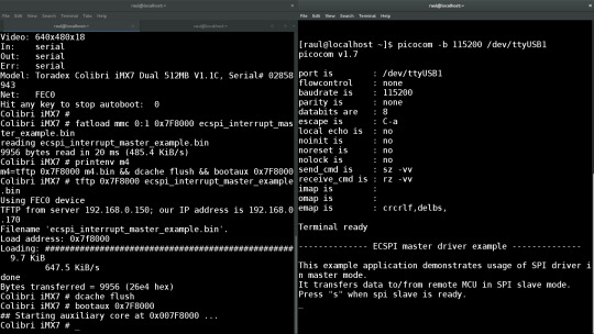
Before typing “s” in the UART B terminal, prepare a loop-back between SPI MISO and MOSI pins. Thus, it will be possible to see the communication in loop-back and not only send message but also receive data in the SPI.
-------------- ECSPI master driver example -------------- This example application demonstrates usage of SPI driver in master mode. It transfers data to/from remote MCU in SPI slave mode. Press "s" when spi slave is ready. MASTER: Transmited data: 1 : Received data: 1 MASTER: Transmited data: 2 : Received data: 2 ... ... ... MASTER: Transmited data: 19 : Received data: 19 MASTER: Transmited data: 20 : Received data: 20
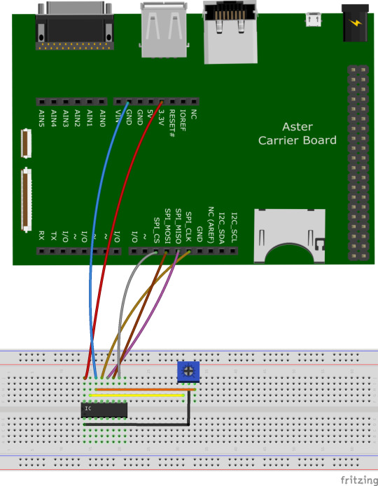
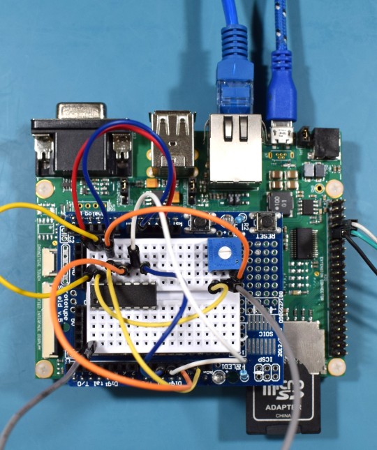
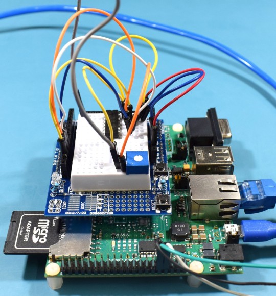
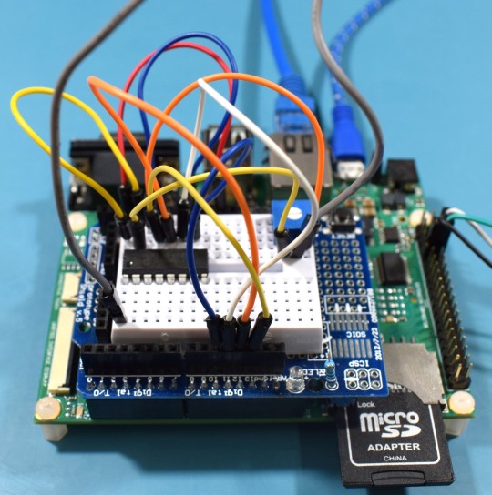
Practical example - SPI
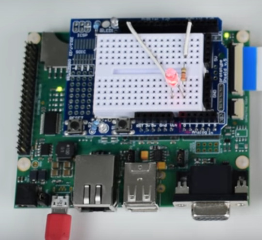
In the previous example, we only compiled and executed the code. Now, let’s modify the code to communicate via SPI with the chip MCP3008 from Microchip. This chip is a 10-bit Analog to Digital converter with 8 single ended inputs. Connect the wires to the Aster and to a breadboard as presented in the picture below:
For those who prefer to use the Eclipse IDE, it is possible to use CMake to generate Eclipse project files. The Cmake -G parameter allows to configure a “build system generator”. Make sure that “build_all.sh” specifies the “Eclipse CDT4 – Unix Makefiles” generator.
In the armgcc sample directory:
[raul@localhost armgcc]$ vi build_all.sh
#!/bin/sh cmake -DCMAKE_TOOLCHAIN_FILE="../../../../../../../tools/cmake_toolchain_files/armgcc.cmake" -G "Eclipse CDT4 - Unix Makefiles" -DCMAKE_BUILD_TYPE=Debug . make -j4 cmake -DCMAKE_TOOLCHAIN_FILE="../../../../../../../tools/cmake_toolchain_files/armgcc.cmake" -G "Eclipse CDT4 - Unix Makefiles" -DCMAKE_BUILD_TYPE=Release . make -j4
Next, execute again the “build_all.sh” script:
[raul@localhost armgcc]$ ./build_all.sh [raul@localhost armgcc]$ ls .cproject .project .cproject .project
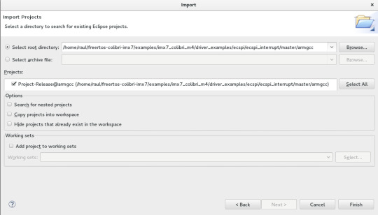
Open Eclipse and import the project:
File > Import…
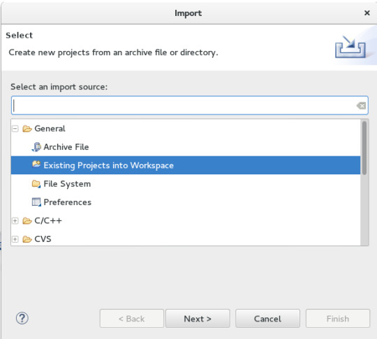
In “Select root directory”, enter the path of the “armgcc” folder of your project:
/home/raul/freertos-colibri-imx7/examples/imx7_colibri_m4/driver_examples/ecspi/ecspi_interrupt/master/armgcc
Open the file “main.c” in the directory.
[TARGET] → [exec]ecspi_interrupt_master_example → Source Files
Note that the standard example is quite simple. It is important to show some points of the code to understand clearly where to look in the next examples.
int main(void) { uint8_t control_char; uint8_t i; ecspi_init_config_t ecspiMasterInitConfig = { .baudRate = 500000, .mode = ecspiMasterMode, .burstLength = ECSPI_MASTER_BURSTLENGTH, .channelSelect = BOARD_ECSPI_CHANNEL, .clockPhase = ecspiClockPhaseSecondEdge, .clockPolarity = ecspiClockPolarityActiveHigh, .ecspiAutoStart = ECSPI_MASTER_STARTMODE }; /* Hardware initialize, include RDC, CLOCK, IOMUX, ENABLE MODULE */ hardware_init(); /* Update clock frequency of this module */ ecspiMasterInitConfig.clockRate = get_ecspi_clock_freq(BOARD_ECSPI_BASEADDR); PRINTF("\n-------------- ECSPI master driver example --------------\n\n\r"); PRINTF("This example application demonstrates usage of SPI driver in master mode.\n\r"); PRINTF("It transfers data to/from remote MCU in SPI slave mode.\n\r"); /* Ecspi module initialize, include configure parameters */ ECSPI_MasterConfig(&ecspiMasterInitConfig); /* Wait slave ready, then press 's' to start communication. */ while(true) { PRINTF("Press \"s\" when spi slave is ready.\n\r"); control_char = GETCHAR(); if((control_char == 's') || (control_char == 'S')) break; } /* Send 1~20 to slave and receive data from slave */ for(i = 0; i < 20; i++) { txData[0]++; ECSPI_MasterTransfer((uint8_t*)txData, (uint8_t*)rxData, 1); while(ECSPI_MasterGetTransferStatus()); PRINTF("MASTER: Transmited data: %d \n\r", txData[0]); PRINTF(" : Received data: %d \n\n\r", rxData[0]); } while(1); }
The first item that is interesting to note is where the pin multiplexing configuration occurs. In our case, we are using the standard SPI. Right–click on the “hardware_init();” function and select “Open Declaration”
void hardware_init(void) { /* Board specific RDC settings */ BOARD_RdcInit(); /* Board specific clock settings */ BOARD_ClockInit(); /* initialize debug uart */ dbg_uart_init(); /* RDC ECSPI */ RDC_SetPdapAccess(RDC, BOARD_ECSPI_RDC_PDAP, 3 << (BOARD_DOMAIN_ID * 2), false, false); /* Select board ecspi clock derived from OSC clock(24M) */ CCM_UpdateRoot(CCM, BOARD_ECSPI_CCM_ROOT, ccmRootmuxEcspiOsc24m, 0, 0); /* Enable ecspi clock gate */ CCM_EnableRoot(CCM, BOARD_ECSPI_CCM_ROOT); CCM_ControlGate(CCM, BOARD_ECSPI_CCM_CCGR, ccmClockNeededAll); /* Configure ecspi pin IOMUX */ configure_ecspi_pins(BOARD_ECSPI_BASEADDR); }
Note that the main hardware initialization /configuration are in this function. The configuration of the SPI pins is in the last function, called “configure_ecspi_pins(BOARD_ECSPI_BASEADDR);”.
void configure_ecspi_pins(ECSPI_Type* base) { // ECSPI1 iomux configuration /* daisy chain selection */ IOMUXC_ECSPI3_MISO_SELECT_INPUT = 0; //(I2C1_SCL SODIM 90) IOMUXC_ECSPI3_MOSI_SELECT_INPUT = 0; //(I2C1_SCL SODIM 90) /* iomux */ IOMUXC_SW_MUX_CTL_PAD_I2C2_SCL = IOMUXC_SW_MUX_CTL_PAD_I2C2_SCL_MUX_MODE(3); /* ECSPI SLK */ IOMUXC_SW_MUX_CTL_PAD_I2C1_SDA = IOMUXC_SW_MUX_CTL_PAD_I2C1_SDA_MUX_MODE(3); /* ECSPI MOSI */ IOMUXC_SW_MUX_CTL_PAD_I2C1_SCL = IOMUXC_SW_MUX_CTL_PAD_I2C1_SCL_MUX_MODE(3); /* ECSPI MISO */ IOMUXC_SW_MUX_CTL_PAD_I2C2_SDA = IOMUXC_SW_MUX_CTL_PAD_I2C2_SDA_MUX_MODE(3); /* ECSPI SS0 */ /* pad control */ IOMUXC_SW_PAD_CTL_PAD_I2C2_SCL = IOMUXC_SW_PAD_CTL_PAD_I2C2_SCL_PE_MASK | IOMUXC_SW_PAD_CTL_PAD_I2C2_SCL_PS(0) | /* pull down */ IOMUXC_SW_PAD_CTL_PAD_I2C2_SCL_DSE(0) | IOMUXC_SW_PAD_CTL_PAD_I2C2_SCL_HYS_MASK; IOMUXC_SW_PAD_CTL_PAD_I2C1_SDA = IOMUXC_SW_PAD_CTL_PAD_I2C1_SDA_DSE(0) | IOMUXC_SW_PAD_CTL_PAD_I2C1_SDA_HYS_MASK; IOMUXC_SW_PAD_CTL_PAD_I2C1_SCL = IOMUXC_SW_PAD_CTL_PAD_I2C1_SCL_HYS_MASK; IOMUXC_SW_PAD_CTL_PAD_I2C2_SDA = IOMUXC_SW_PAD_CTL_PAD_I2C2_SDA_PE_MASK | IOMUXC_SW_PAD_CTL_PAD_I2C2_SDA_PS(3) | /* pull up */ IOMUXC_SW_PAD_CTL_PAD_I2C2_SDA_DSE(0) | IOMUXC_SW_PAD_CTL_PAD_I2C2_SDA_HYS_MASK; }
Another important file is “board.h”. If in the same function, you search for the definition of "BOARD_ECSPI_BASEADDR" in "configure_ecspi_pins (BOARD_ECSPI_BASEADDR);" you will see a part of the file “board.h” which sets up more things related to SPI, for example the interruption vector.
/* Colibri SPI is ECSPI3 */ #define BOARD_ECSPI_RDC_PDAP rdcPdapEcspi3 #define BOARD_ECSPI_CCM_ROOT ccmRootEcspi3 #define BOARD_ECSPI_CCM_CCGR ccmCcgrGateEcspi3 #define BOARD_ECSPI_BASEADDR ECSPI3 #define BOARD_ECSPI_CHANNEL ecspiSelectChannel0 #define BOARD_ECSPI_IRQ_NUM eCSPI3_IRQn #define BOARD_ECSPI_HANDLER eCSPI3_Handler
Returning to “main.c”, we will change the main loop to get the data from MCP3008. More specifically, we will read the channel 0 of the chip.
/* Wait slave ready, then press 's' to start communication. */ while(true) { PRINTF("Press \"s\" when spi slave is ready.\n\r"); control_char = GETCHAR(); if((control_char == 's') || (control_char == 'S')) break; }
Remove the “break” and add the code below. According the datasheet of MCP3008, the sequence “00000001 10000000 00000000”, which means the start bit, channel selection and the complement of information to form 10 bits of data, respectively.
/* Wait slave ready, then press 's' to start communication. */ while(true) { PRINTF("Press \"s\" when spi slave is ready.\n\r"); control_char = GETCHAR(); if((control_char == 's') || (control_char == 'S')) { unsigned char datatx[3]; unsigned char datarx[3]; datatx[0] = 0b00000001; // first byte transmitted -> start bit datatx[1] = 0b10000000; // second byte transmitted -> (SGL/DIF = 1, D2=D1=D0=0) datatx[2] = 0b00000000; // third byte transmitted....don't care /* SPI Read */ ECSPI_MasterTransfer((uint8_t*)&datatx[0], (uint8_t*)&datarx[0], 3); while(ECSPI_MasterGetTransferStatus()); PRINTF("Transmited data: %d \n\r", datatx[0]); PRINTF("Transmited data: %d \n\r", datatx[1]); PRINTF("Transmited data: %d \n\r", datatx[2]); PRINTF("Received data: %d \n\n\r", datarx[0]); PRINTF("Received data: %d \n\n\r", datarx[1]); PRINTF("Received data: %d \n\n\r", datarx[2]); unsigned int a2dVal = 0; a2dVal = (datarx[1]<< 8) & 0b1100000000; //merge data[1] & data[2] to get result a2dVal |= (datarx[2] & 0xff); PRINTF("data = %d \n\n\r", a2dVal); } }
After changing the example, the function “int main (void)” should look like this:
int main(void) { uint8_t control_char; uint8_t i; ecspi_init_config_t ecspiMasterInitConfig = { .baudRate = 500000, .mode = ecspiMasterMode, .burstLength = ECSPI_MASTER_BURSTLENGTH, .channelSelect = BOARD_ECSPI_CHANNEL, .clockPhase = ecspiClockPhaseSecondEdge, .clockPolarity = ecspiClockPolarityActiveHigh, .ecspiAutoStart = ECSPI_MASTER_STARTMODE }; /* Hardware initialize, include RDC, CLOCK, IOMUX, ENABLE MODULE */ hardware_init(); /* Update clock frequency of this module */ ecspiMasterInitConfig.clockRate = get_ecspi_clock_freq(BOARD_ECSPI_BASEADDR); PRINTF("\n-------------- ECSPI master driver example --------------\n\n\r"); PRINTF("This example application demonstrates usage of SPI driver in master mode.\n\r"); PRINTF("It transfers data to/from remote MCU in SPI slave mode.\n\r"); /* Ecspi module initialize, include configure parameters */ ECSPI_MasterConfig(&ecspiMasterInitConfig); /* Wait slave ready, then press 's' to start communication. */ while(true) { PRINTF("Press \"s\" when spi slave is ready.\n\r"); control_char = GETCHAR(); if((control_char == 's') || (control_char == 'S')) { unsigned char datatx[3]; unsigned char datarx[3]; datatx[0] = 0b00000001; // first byte transmitted -> start bit datatx[1] = 0b10000000; // second byte transmitted -> (SGL/DIF = 1, D2=D1=D0=0) datatx[2] = 0b00000000; // third byte transmitted....don't care /* SPI Read */ ECSPI_MasterTransfer((uint8_t*)&datatx[0], (uint8_t*)&datarx[0], 3); while(ECSPI_MasterGetTransferStatus()); PRINTF("Transmited data: %d \n\r", datatx[0]); PRINTF("Transmited data: %d \n\r", datatx[1]); PRINTF("Transmited data: %d \n\r", datatx[2]); PRINTF("Received data: %d \n\n\r", datarx[0]); PRINTF("Received data: %d \n\n\r", datarx[1]); PRINTF("Received data: %d \n\n\r", datarx[2]); unsigned int a2dVal = 0; a2dVal = (datarx[1]<< 8) & 0b1100000000; //merge data[1] & data[2] to get result a2dVal |= (datarx[2] & 0xff); PRINTF("data = %d \n\n\r", a2dVal); } } }
Recompile the binary, copy by SD Card or Ethernet according the previous example and execute the binary.
SD Card:
[raul@localhost release]$ df Filesystem 1K-blocks Used Available Use% Mounted on /dev/sdb1 7780496 469540 7310956 7% /run/media/raul/DATA [raul@localhost release]$ cp ecspi_interrupt_master_example.bin /run/media/raul/DATA [raul@localhost release]$ umount /run/media/raul/DATA
Ethernet:
[raul@localhost release]$ cp ecspi_interrupt_master_example.bin /srv/tftp/
Insert the SD card on the board or set up the network and execute the binary.
SD Card:
Colibri iMX7 # fatload mmc 0:1 0x7F8000 ecspi_interrupt_master_example.bin reading ecspi_interrupt_master_example.bin 9956 bytes read in 20 ms (485.4 KiB/s)
Ethernet:
Colibri iMX7 # tftp 0x7F8000 ecspi_interrupt_master_example.bin Using FEC0 device TFTP from server 192.168.0.150; our IP address is 192.168.0.170 Filename 'ecspi_interrupt_master_example.bin'. Load address: 0x7f8000 Loading: ################################################## 9.7 KiB 647.5 KiB/s done Bytes transferred = 9956 (26e4 hex)
Once the firmware is loaded properly, it does not matter which method you are using, run the command to execute the binary loaded on Cortex-M.
Colibri iMX7 # dcache flush Colibri iMX7 # bootaux 0x7F8000 ## Starting auxiliary core at 0x007F8000 ... Colibri iMX7 #
New with the alternate version of the code, pressing the bottom “s” on terminal UART B shows a new analog acquisition on channel 0.
Conflicts with Linux
After these U-boot commands, you may want to run the “boot” command to boot the Linux. The problem is that our example is using the UART B and the SPI. To start the Linux without problem, it is necessary to modify the device tree to tell Linux to not use these resources.
To temporarily disable UART B and SPI without changing the device tree, you can use the U-boot command below:
Colibri iMX7 # setenv fdt_fixup 'fdt addr ${fdt_addr_r} && fdt rm /soc/aips-bus@30800000/spba-bus@30800000/serial@30890000 && fdt rm /soc/aips-bus@30800000/spba-bus@30800000/ecspi@30840000' Colibri iMX7 # saveenv Saving Environment to NAND... Erasing NAND... Erasing at 0x380000 -- 100% complete. Writing to NAND... OK
More information about device tree customization is available in this article on the Toradex Developer Website
Automated deployment
In my case, I used to load the binary of Cortex-M by Ethernet. An interesting way to save time is to automate the copy of the binary to the “/dev/tftp/” directory. To do this, at the root of you project, open the file:
raul@localhost master]$ vi armgcc/CMakeLists.txt
Add the following line at the end of the file:
[raul@localhost master]$ vi armgcc/CMakeLists.txt ADD_CUSTOM_COMMAND(TARGET ${Project_Name}_Main POST_BUILD COMMAND cp ${EXECUTABLE_OUTPUT_PATH}/ecspi_interrupt_master_example.bin /srv/tftp/m4.bin)
Run the script “./build_all.sh” again and when compiling by eclipse, you should see the command running automatically on the “console”:
cp /home/raul/freertos-colibri-imx7/examples/imx7_colibri_m4/driver_examples/ecspi/ecspi_interrupt/master/armgcc/release/ecspi_interrupt_master_example.bin /srv/tftp/m4.bin
Another optimization that helped me a lot was to create the automatic rule in U-boot to load the binary:
Colibri iMX7 # setenv m4 'tftp 0x7F8000 m4.bin && dcache flush && bootaux 0x7F8000' Colibri iMX7 # setenv bootcmd 'run m4; run ubiboot; setenv fdtfile ${soc}-colibri-${fdt_board}.dtb && run distro_bootcmd;'
Now, every time you turn on the module, it will automatically load the binary and then upload Linux.
Conclusion
In this article, it was possible to learn some of the first steps to implement solutions on heterogeneous multicore processor architecture. Through two examples, we saw how to compile and run codes on the Cortex-M4 of an HMP SoC on the Colibri iMX7 Computer on Module. We also learned that the different cores inside the SoC share the peripheral interfaces, so it is necessary to understand (and plan) which peripheral will be assigned to each core.
#Toradex Blog#Embedded Application Development#Heterogeneous Multi-core#Multi-core Processors#Embedded Systems#Computer on Modules
0 notes
Text
Starting with OpenCV on i.MX 6 Processors
Introduction
As the saying goes, a picture is worth a thousand words. It is indeed true to some extent: a picture can hold information about objects, environment, text, people, age and situations, among other information. It can also be extended to video, that can be interpreted as a series of pictures and thus holds motion information.
This might be a good hint as to why computer vision (CV) has been a field of study that is expanding its boundaries every day. But then we come to the question: what is computer vision? It is the ability to extract meaning from an image, or a series of images. It is not to be confused with digital imaging neither image processing, which are the production of an input image and the application of mathematical operations to images, respectively. Indeed, they are both required to make CV possible.
But what might be somehow trivial to human beings, such as reading or recognizing people, is not always true when talking about computers interpreting images. Although nowadays there are many well known applications such as face detection in digital cameras and even face recognition in some systems, or optical character recognition (OCR) for book scanners and license plate reading in traffic monitoring systems, these are fields that nearly didn't exist 15 years ago in people's daily lives. Self-driving cars going from controlled environments to the streets are a good measure of how cutting-edge this technology is, and one of the enablers of CV is the advancement of computing power in smaller packages.
Being so, this blog post is an introduction to the use of computer vision in embedded systems, by employing the OpenCV 2.4 and 3.1 versions in Computer on Modules (CoMs) equipped with NXP i.MX 6 processors. The CoMs chosen were the Colibri and Apalis families from Toradex.
OpenCV stands for Open Source Computer Vision Library, which is a set of libraries that contain several hundreds of computer vision related algorithms. It has a modular structure, divided in a core library and several others such as image processing module, video analysis module and user interface capabilities module, among others.
Considerations about OpenCV, i.MX 6 processors and the Toradex modules
OpenCV is a set of libraries that computes mathematical operations on the CPU by default. It has support for multicore processing by using a few external libraries such as OpenMP (Open Multi-processing) and TBB (Threading Building Blocks). This blog post will not go deeper into comparing the implementation aspects of the choices available, but the performance of a specific application might change with different libraries.
Regarding support for the NEON floating-point unit coprocessor, the release of OpenCV 3.0 states that approximately 40 functions have been accelerated and a new HAL (hardware abstraction layer) provides an easy way to create NEON-optimized code, which is a good way to enhance performance in many ARM embedded systems. I didn't dive deep into it, but if you like to see under the hood, having a look at the OpenCV source-code (1, 2) might be interesting.
This blog post will present how to use OpenCV 2.4 and also OpenCV 3.1 - this was decided because there might be readers with legacy applications that want to use the older version. It is a good opportunity for you to compare performance between versions and have a hint about the NEON optimizations gains.
The i.MX 6 single/dual lite SoC has graphics GPU (GC880) which supports OpenGL ES, while the i.MX 6 dual/quad SoC, has 3D graphics GPU (GC2000) which supports OpenGL ES and also OpenCL Embedded Profile, but not the Full Profile. The i.MX 6 also has 2D GPU (GC320), IPU and, for the dual/quad version, vector GPU (GC335), but this blog post will not discuss the possibility of using these hardware capabilities with OpenCV - it suffices to say that OpenCV source-code does not support them by default, therefore a considerable amount of effort would be required to take advantage of the i.MX 6 hardware specifics.
While OpenCL is a general purpose GPU programming language, its use is not the target of this blog post. OpenGL is an API for rendering 2D and 3D graphics on the GPU, and therefore is not meant for general purpose computing, although some experiments (1) have demonstrated that it is possible to use OpenGL ES for general purpose image processing, and there is even an application-note by NXP for those interested. If you would like to use GPU accelerated OpenCV out-of-the-box, Toradex has a module that supports CUDA – the Apalis TK1. See this blog post for more details.
Despite all the hardware capabilities available and possibly usable to gain performance, according to this presentation, the optimization of OpenCV source-code focusing only software and the NEON co-processor could yield a performance enhancement of 2-3x for algorithm and another 3-4x NEON optimizations.
The Images 1 and 2 present, respectively, the Colibri iMX6DL + Colibri Evaluation Board and the Apalis iMX6Q + Apalis Evaluation Board, both with supply, debug UART, ethernet, USB camera and VGA display cables plugged in.
Colibri iMX6DL Colibri Evaluation Board setup
Apalis iMX6Q Apalis Evaluation Board setup
It is important to notice that different USB camera models had a performance offset, and that the camera employed in this blog post is a generic consumer camera – the driver was listed as “Aveo Technology Corp”. There are also professional cameras in the market, USB or not, such as the solutions provided by Basler AG, that are meant for embedded solutions when going to develop a real-world solution.
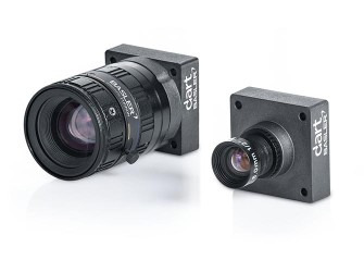
Professional camera from Basler AG
In addition, Toradex has the CSI Camera Module 5MP OV5640. It is an add-on board for the Apalis computer-on-module which uses MIPI-CSI Interface. It uses the OmniVision OV5640 camera sensor with built-in auto-focus. The OV5640 image sensor is a low voltage, high-performance, 1/4-inch 5 megapixel CMOS image sensor that provides the full functionality of a single chip 5 megapixel (2592x1944) camera. The CSI Camera Module 5MP OV5640 can be connected to the MIPI-CSI connector on the Ixora carrier board V1.1 using a 24 way 0.5mm pitch FFC cable.

Toradex CSI Camera Module 5MP OV5640
At the end of this blog post, a summary of the instructions to install OpenCV and deploy applications to the target is provided.
Building Linux image with OpenCV
Images for the OpenCV 2.4 and 3.1 are built with OpenEmbedded. You may follow this article to set up your host machine. The first step required is to install the system prerequisites for OpenEmbedded. Below an example is given for Ubuntu 16.04 - for other versions of Ubuntu and Fedora, please refer to the article link above:
sudo dpkg --add-architecture i386 sudo apt-get update sudo apt-get install g++-5-multilib sudo apt-get install curl dosfstools gawk g++-multilib gcc-multilib lib32z1-dev libcrypto++9v5:i386 libcrypto++-dev:i386 liblzo2-dev:i386 libstdc++-5-dev:i386 libusb-1.0-0:i386 libusb-1.0-0-dev:i386 uuid-dev:i386 cd /usr/lib; sudo ln -s libcrypto++.so.9.0.0 libcryptopp.so.6
The repo utility must also be installed, to fetch the various git repositories required to build the images:
mkdir ~/bin export PATH=~/bin:$PATH curl http://commondatastorage.googleapis.com/git-repo-downloads/repo > ~/bin/repo chmod a+x ~/bin/repo
Let's build the images with OpenCV 2.4 and 3.1 in different directories. If you are interested in only one version, some steps might be omitted. A directory to share the content downloaded by OpenEmbedded will also be created:
cd mkdir oe-core-opencv2.4 oe-core-opencv3.1 oe-core-downloads cd oe-core-opencv2.4 repo init -u http://git.toradex.com/toradex-bsp-platform.git -b LinuxImageV2.6.1 repo sync cd ../oe-core-opencv3.1 repo init -u http://git.toradex.com/toradex-bsp-platform.git -b LinuxImageV2.7 repo sync
OpenCV 2.4
OpenCV 2.4 will be included in the Toradex base image V2.6.1. Skip this section and go to the OpenCV3.1 if you are not interested in this version. The recipe included by
default uses the version 2.4.11 and has no support for multicore processing included.
Remove the append present in the meta-fsl-arm and the append present in the meta-toradex-demos:
rm layers/meta-fsl-arm/openembedded-layer/recipes-support/opencv/opencv_2.4.bbappend rm layers/meta-toradex-demos/recipes-support/opencv/opencv_2.4.bbappend
Let's create an append to use the version 2.4.13.2 (latest version so far) and add TBB as the framework to take advantage of multiple cores. Enter the oe-core-opencv2.4 directory:
cd oe-core-opencv2.4
Let's create an append in the meta-toradex-demos layer (layers/meta-toradex-demos/recipes-support/opencv/opencv_2.4.bbappend) with the following content:
gedit layers/meta-toradex-demos/recipes-support/opencv/opencv_2.4.bbappend ------------------------------------------------------------------------------------- SRCREV = "d7504ecaed716172806d932f91b65e2ef9bc9990" SRC_URI = "git://github.com/opencv/opencv.git;branch=2.4" PV = "2.4.13.2+git${SRCPV}" PACKAGECONFIG += " tbb" PACKAGECONFIG[tbb] = "-DWITH_TBB=ON,-DWITH_TBB=OFF,tbb,"
Alternatively, OpenMP could be used instead of TBB:
gedit layers/meta-toradex-demos/recipes-support/opencv/opencv_2.4.bbappend ------------------------------------------------------------------------------------- SRCREV = "d7504ecaed716172806d932f91b65e2ef9bc9990" SRC_URI = "git://github.com/opencv/opencv.git;branch=2.4" PV = "2.4.13.2+git${SRCPV}" EXTRA_OECMAKE += " -DWITH_OPENMP=ON"
Set up the environment before configuring the machine and adding support for OpenCV. Source the export script that is inside the oe-core-opencv2.4 directory:
. export
You will automatically enter the build directory. Edit the conf/local.conf file to modify and/or add the variables below:
gedit conf/local.conf ------------------------------------------------------------------------------- MACHINE ?= "apalis-imx6" # or colibri-imx6 depending on the CoM you have # Use the previously created folder for shared downloads, e.g. DL_DIR ?= "/home/user/oe-core-downloads" ACCEPT_FSL_EULA = "1" # libgomp is optional if you use TBB IMAGE_INSTALL_append = " opencv opencv-samples libgomp"
After that you can build the image, which takes a while:
bitbake –k angstrom-lxde-image
OpenCV 3.1
OpenCV 3.1 will be included in the Toradex base image V2.7. This recipe, different from the 2.4, already has TBB support included. Still, a compiler flag must be added or the compiling process will fail. Enter the oe-core-opencv3.1 directory:
cd oe-core-opencv3.1
Create a recipe append (layers/meta-openembedded/meta-oe/recipes-support/opencv/opencv_3.1.bb) with the following contents:
gedit layers/meta-toradex-demos/recipes-support/opencv/opencv_3.1.bbappend ------------------------------------------------------------------------------------- CXXFLAGS += " -Wa,-mimplicit-it=thumb"
Alternatively, OpenMP could be used instead of TBB. If you want to do it, create the bbappend with the following contents:
gedit layers/meta-toradex-demos/recipes-support/opencv/opencv_3.1.bbappend ------------------------------------------------------------------------------------- CXXFLAGS_armv7a += " -Wa,-mimplicit-it=thumb" PACKAGECONFIG_remove = "tbb" EXTRA_OECMAKE += " -DWITH_OPENMP=ON"
Set up the environment before configuring the machine and adding support for OpenCV. Source the export script that is inside the oe-core-opencv3.1 directory:
. export
You will automatically enter the build directory. Edit the conf/local.conf file to modify and/or add the variables below:
gedit conf/local.conf ------------------------------------------------------------------------------- MACHINE ?= "apalis-imx6" # or colibri-imx6 depending on the CoM you have # Use the previously created folder for shared downloads, e.g. DL_DIR ?= "/home/user/oe-core-downloads" ACCEPT_FSL_EULA = "1" # libgomp is optional if you use TBB IMAGE_INSTALL_append = " opencv libgomp"
After that you can build the image, which will take a while:
bitbake –k angstrom-lxde-image
Update the module
The images for both OpenCV versions will be found in the oe-core-opencv<version>/deploy/images/<board_name> directory, under the name <board_name>_LinuxImage<image_version>_<date>.tar.bz2. Copy the compressed image to some project directory in your computer, if you want. An example is given below for Apalis iMX6 with OpenCV 2.4, built in 2017/01/26:
cd /home/user/oe-core-opencv2.4/deploy/images/apalis-imx6/ cp Apalis_iMX6_LinuxImageV2.6.1_20170126.tar.bz2 /home/root/myProjectDir cd /home/root/myProjectDir
Please follow this article's instructions to update your module.
Generating SDK
To generate an SDK, that will be used to cross-compile applications, run the following command:
bitbake –c populate_sdk angstrom-lxde-image
After the process is complete, you will find the SDK under /deploy/sdk. Run the script to install – you will be prompted to chose an installation path:
./angstrom-glibc-x86_64-armv7at2hf-vfp-neon-v2015.12-toolchain.sh Angstrom SDK installer version nodistro.0 ========================================= Enter target directory for SDK (default: /usr/local/oecore-x86_64):
In the next steps it will be assumed that you are using the following SDK directories:
For OpenCV 2.4: /usr/local/oecore-opencv2_4
For OpenCV 3.1: /usr/local/oecore-opencv3_1
Preparing for cross-compilation
After the installation is complete, you can use the SDK to compile your applications. In order to generate the Makefiles, CMake was employed. If you don't have CMake, install it:
sudo apt-get install cmake
Create a file named CMakeLists.txt inside your project folder, with the content below. Please make sure that the sysroot name inside your SDK folder is the same as the one in the script (e.g. armv7at2hf-vfp-neon-angstrom-linux-gnueabi):
cd ~ mkdir my_project gedit CMakeLists.txt -------------------------------------------------------------------------------- cmake_minimum_required(VERSION 2.8) project( MyProject ) set(CMAKE_RUNTIME_OUTPUT_DIRECTORY "${CMAKE_BINARY_DIR}/bin") add_executable( myApp src/myApp.cpp ) if(OCVV EQUAL 2_4) message(STATUS "OpenCV version required: ${OCVV}") SET(CMAKE_PREFIX_PATH /usr/local/oecore-opencv${OCVV}/sysroots/armv7at2hf-vfp-neon-angstrom-linux-gnueabi) elseif(OCVV EQUAL 3_1) message(STATUS "OpenCV version required: ${OCVV}") SET(CMAKE_PREFIX_PATH /usr/local/oecore-opencv${OCVV}/sysroots/armv7at2hf-neon-angstrom-linux-gnueabi) else() message(FATAL_ERROR "OpenCV version needs to be passed. Make sure it matches your SDK version. Use -DOCVV=<version>, currently supported 2_4 and 3_1. E.g. -DOCVV=3_1") endif() SET(OpenCV_DIR ${CMAKE_PREFIX_PATH}/usr/lib/cmake/OpenCV) find_package( OpenCV REQUIRED ) include_directories( ${OPENCV_INCLUDE_DIRS} ) target_link_libraries( myApp ${OPENCV_LIBRARIES} )
It is also needed to have a CMake file to point where are the includes and libraries. For that we will create one CMake script inside each SDK sysroot. Let's first do it for the 2.4 version:
cd /usr/local/oecore-opencv2_4/sysroots/armv7at2hf-vfp-neon-angstrom-linux-gnueabi/usr/lib/cmake mkdir OpenCV gedit OpenCV/OpenCVConfig.cmake ----------------------------------------------------------------------------------- set(OPENCV_FOUND TRUE) get_filename_component(_opencv_rootdir ${CMAKE_CURRENT_LIST_DIR}/../../../ ABSOLUTE) set(OPENCV_VERSION_MAJOR 2) set(OPENCV_VERSION_MINOR 4) set(OPENCV_VERSION 2.4) set(OPENCV_VERSION_STRING "2.4") set(OPENCV_INCLUDE_DIR ${_opencv_rootdir}/include) set(OPENCV_LIBRARY_DIR ${_opencv_rootdir}/lib) set(OPENCV_LIBRARY -L${OPENCV_LIBRARY_DIR} -lopencv_calib3d -lopencv_contrib -lopencv_core -lopencv_features2d -lopencv_flann -lopencv_gpu -lopencv_highgui -lopencv_imgproc -lopencv_legacy -lopencv_ml -lopencv_nonfree -lopencv_objdetect -lopencv_ocl -lopencv_photo -lopencv_stitching -lopencv_superres -lopencv_video -lopencv_videostab) if(OPENCV_FOUND) set( OPENCV_LIBRARIES ${OPENCV_LIBRARY} ) set( OPENCV_INCLUDE_DIRS ${OPENCV_INCLUDE_DIR} ) endif() mark_as_advanced(OPENCV_INCLUDE_DIRS OPENCV_LIBRARIES)
The same must be done for the 3.1 version - notice that the libraries change from OpenCV 2 to OpenCV 3:
cd /usr/local/oecore-opencv3_1/sysroots/armv7at2hf-vfp-neon-angstrom-linux-gnueabi/usr/lib/cmake mkdir OpenCV gedit OpenCV/OpenCVConfig.cmake ----------------------------------------------------------------------------------- set(OPENCV_FOUND TRUE) get_filename_component(_opencv_rootdir ${CMAKE_CURRENT_LIST_DIR}/../../../ ABSOLUTE) set(OPENCV_VERSION_MAJOR 3) set(OPENCV_VERSION_MINOR 1) set(OPENCV_VERSION 3.1) set(OPENCV_VERSION_STRING "3.1") set(OPENCV_INCLUDE_DIR ${_opencv_rootdir}/include) set(OPENCV_LIBRARY_DIR ${_opencv_rootdir}/lib) set(OPENCV_LIBRARY -L${OPENCV_LIBRARY_DIR} -lopencv_aruco -lopencv_bgsegm -lopencv_bioinspired -lopencv_calib3d -lopencv_ccalib -lopencv_core -lopencv_datasets -lopencv_dnn -lopencv_dpm -lopencv_face -lopencv_features2d -lopencv_flann -lopencv_fuzzy -lopencv_highgui -lopencv_imgcodecs -lopencv_imgproc -lopencv_line_descriptor -lopencv_ml -lopencv_objdetect -lopencv_optflow -lopencv_photo -lopencv_plot -lopencv_reg -lopencv_rgbd -lopencv_saliency -lopencv_shape -lopencv_stereo -lopencv_stitching -lopencv_structured_light -lopencv_superres -lopencv_surface_matching -lopencv_text -lopencv_tracking -lopencv_videoio -lopencv_video -lopencv_videostab -lopencv_xfeatures2d -lopencv_ximgproc -lopencv_xobjdetect -lopencv_xphoto) if(OPENCV_FOUND) set( OPENCV_LIBRARIES ${OPENCV_LIBRARY} ) set( OPENCV_INCLUDE_DIRS ${OPENCV_INCLUDE_DIR} ) endif() mark_as_advanced(OPENCV_INCLUDE_DIRS OPENCV_LIBRARIES)
After that, return to the project folder. You must export the SDK variables and run the CMake script:
# For OpenCV 2.4 source /usr/local/oecore-opencv2_4/environment-setup-armv7at2hf-vfp-neon-angstrom-linux-gnueabi cmake -DOCVV=2_4 . # For OpenCV 3.1 source /usr/local/oecore-opencv3_1/environment-setup-armv7at2hf-neon-angstrom-linux-gnueabi cmake –DOCVV=3_1 .
Cross-compiling and deploying
To test the cross-compilation environment, let's build a hello-world application that reads an image from a file and displays the image on a screen. This code is essentially the same as the one from this OpenCV tutorial:
mkdir src gedit src/myApp.cpp --------------------------------------------------------------------------------- #include #include <opencv2/opencv.hpp> using namespace std; using namespace cv; int main(int argc, char** argv ){ cout << "OpenCV version: " << CV_MAJOR_VERSION << '.' << CV_MINOR_VERSION << "\n"; if ( argc != 2 ){ cout << "usage: ./myApp \n"; return -1; } Mat image; image = imread( argv[1], 1 ); if ( !image.data ){ cout << "No image data \n"; return -1; } bitwise_not(image, image); namedWindow("Display Image", WINDOW_AUTOSIZE ); imshow("Display Image", image); waitKey(0); return 0; }
To compile and deploy, follow the instructions below. The board must have access to the LAN – you may plug an ethernet cable or use a WiFi-USB adapter, for instance. To find out the ip, use the ifconfig command.
make scp bin/myApp root@<board-IP>/home/root # Also copy some image to test! scp <path-to-image>/myimage.jpg root@<board-IP>:/home/root
In the embedded system, run the application:
root@colibri-imx6:~# ./myApp
You must see the image on the screen, as in Image 3:
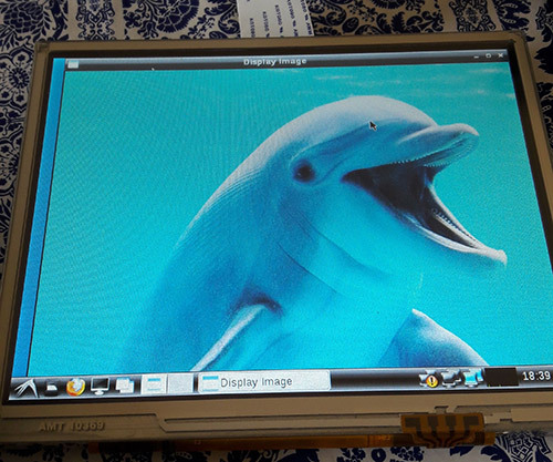
Hello World application
Reading from camera
In this section, a code that reads from the camera and processes the input using the Canny edge detection algorithm will be tested. It is just one out of many algorithms already implemented in OpenCV. By the way, OpenCV has a comprehensive documentation, with tutorials, examples and library references.
In the Linux OS, when a camera device is attached, it can be accessed from the filesystem. The device is mounted in the /dev directory. Let's check the directory contents of Apalis iMX6 before plugging the USB camera:
root@apalis-imx6:~# ls /dev/video* /dev/video0 /dev/video1 /dev/video16 /dev/video17 /dev/video18 /dev/video19 /dev/video2 /dev/video20
And after plugging in:
root@apalis-imx6:~# ls /dev/video* /dev/video0 /dev/video1 /dev/video16 /dev/video17 /dev/video18 /dev/video19 /dev/video2 /dev/video20 /dev/video3
Notice that it is listed as /dev/video3. It can be confirmed using the video4linux2 command-line utility (run v4l2-ctl –help for details):
root@apalis-imx6:~# v4l2-ctl --list-devices [ 3846.876041] ERROR: v4l2 capture: slave not found! V4L2_CID_HUE [ 3846.881940] ERROR: v4l2 capture: slave not found! V4L2_CID_HUE [ 3846.887923] ERROR: v4l2 capture: slave not found! V4L2_CID_HUE DISP4 BG ():[ 3846.897425] ERROR: v4l2 capture: slave not found! V4L2_CID_HUE /dev/video16 /dev/video17 /dev/video18 /dev/video19 /dev/video20 UVC Camera (046d:081b) (usb-ci_hdrc.1-1.1.3): /dev/video3 Failed to open /dev/video0: Resource temporarily unavailable
It is also possible to get the input device parameters. Notice that the webcam used in all the tests has a resolution of 640x480 pixels.
root@apalis-imx6:~# v4l2-ctl -V --device=/dev/video3 Format Video Capture: Width/Height : 640/480 Pixel Format : 'YUYV' Field : None Bytes per Line: 1280 Size Image : 614400 Colorspace : SRGB
In addition, since all of the video interfaces are abstracted by the Linux kernel, if you were using the CSI Camera Module 5MP OV5640 from Toradex, it would be listed as another video interface. On Apalis iMX6 the kernel drivers are loaded by default. For more information, please check this knowledge-base article.
Going to the code, the OpeCV object that does the camera handling, VideoCapture, accepts the camera index (which is 3 for our /dev/video3 example) or -1 to autodetect the camera device.
An infinite loop processes the video frame by frame. Our example applies the filters conversion to gray scale -> Gaussian blur -> Canny and then sends the processed image to the video output. The code is presented below:
#include #include #include <opencv2/core/core.hpp> #include <opencv2/imgproc/imgproc.hpp> #include <opencv2/highgui/highgui.hpp> using namespace std; using namespace cv; int main(int argc, char** argv ){ cout << "OpenCV version: " << CV_MAJOR_VERSION << '.' << CV_MINOR_VERSION << '\n'; VideoCapture cap(-1); // searches for video device if(!cap.isOpened()){ cout << "Video device could not be opened\n"; return -1; } Mat edges; namedWindow("edges",1); double t_ini, fps; for(; ; ){ t_ini = (double)getTickCount(); // Image processing Mat frame; cap >> frame; // get a new frame from camera cvtColor(frame, edges, COLOR_BGR2GRAY); GaussianBlur(edges, edges, Size(7,7), 1.5, 1.5); Canny(edges, edges, 0, 30, 3); // Display image and calculate current FPS imshow("edges", edges); if(waitKey(30) >= 0) break; fps = getTickFrequency()/((double)getTickCount() - t_ini); cout << "Current fps: " << fps << '\r' << flush; } return 0; }
Image 4 presents the result. Notice that neighter the blur nor the Canny algorithms parameters were tuned.
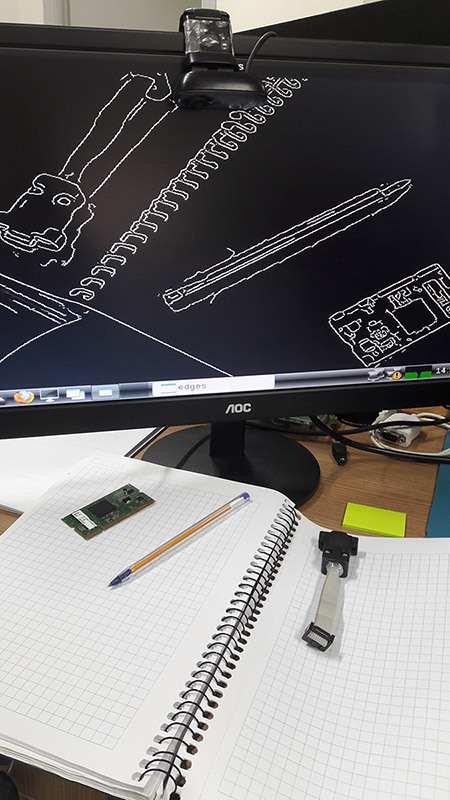
Capture from USB camera being processed with Canny edge detection
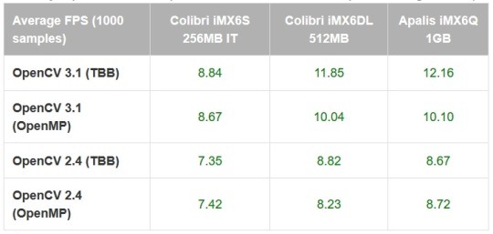
In order to compare between the Colibri iMX6S and iMX6DL and be assured that multicore processing is being done, the average FPS for 1000 samples was measured, and is presented in table 1. It was also done for the Apalis iMX6Q with the Apalis Heatsink. All of the tests had frequency scaling disabled.
Table 1 – Canny implementation comparison between modules and OpenCV configurations (640x480)
As a comparison, the Canny algorithm was replaced in the code with the Sobel derivatives, based on this example. The results are presented in table 2:
Table 2 – Sobel implementation comparison between modules and OpenCV configurations (640x480)
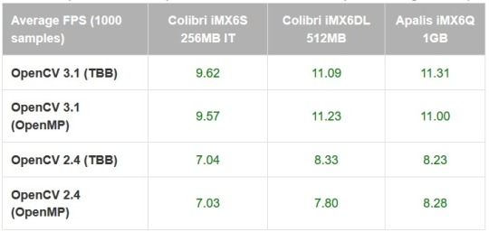
It is interesting to notice that using the TBB framework may be slightly faster than OpenMP in most of the situations, but not always. It is interesting to notice that there is a small performance difference even for the single-core results.
Also, the enhancements made from OpenCV 2.4 to OpenCV 3.1 have a significant impact in the applications performance – which might be explained by the NEON optimizations made so far, and also an incentive to try to optimize the algorithms that your application requires. Based on this preliminary results, it is interesting to test a specific application with several optimization combinations and using only the latest OpenCV version before deploying.
Testing an OpenCV face-tracking sample
There is also a face-tracking sample in the OpenCV source-code that was tested, since it is heavier than the previously made tests and might provide a better performance awareness regarding Colibri x Apalis when choosing the more appropriate hardware for your project.
The first step was to copy the application source-code from GitHub and replace the contents of myApp.cpp, or create another file and modify the CMake script if you prefer. You will also need the Haar cascades provided for face and eye recognition. You might as well clone the whole OpenCV git directory and later test other samples.
A few changes must be made in the source-code so it also works for OpenCV2.4: include the stdio.h library, modify the OpenCV included libraries (take a look in the new headers layout section here) and make some changes to the CommandLineParser, since the versions from OpenCV 2 and 3 are not compatible. Image 5 presents the application running:
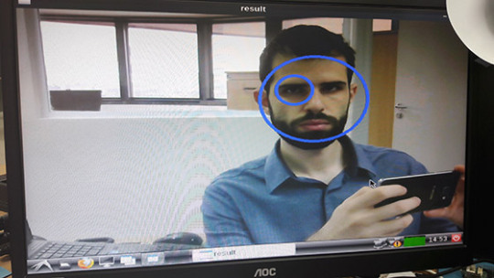
Face and eye tracking application
The code already prints the time it takes to run a face detection. Table 3, presented below, holds the results for 100 samples:
Table 3 – Face detection comparison between modules and OpenCV configurations (640x480)
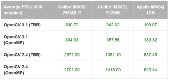
Again the difference between OpenCV versions is not negligible - for the Apalis iMX6Q (quad-core) the performance gain is 3x, and using OpenCV 3.1 with the dual-core Colibri iMX6DL delivers a better performance than OpenCV 2.4 with the quad-core Apalis iMX6Q.
The single-core IT version, thus with reduced clock compared to the others, has results far behind as expected. The reduced clock may explain why the performance improvement from single to dual core is higher than dual to quad core.
Conclusion
Since OpenCV is nowadays (probably) the most popular set of libraries for computer vision, and with the enhancement of performance in embedded systems, knowing how to start with OpenCV for embedded applications provides a powerful tool to solve problems of nowadays and the near future.
This blog post has chosen a widely known family of microprocessors as an example and a starting point, be for those only studying computer vision or those already focusing on developing real-world applications. It also has demonstrated that things are only starting – see for instance the performance improvements from OpenCV 2 to 3 for ARM processors – which also points towards the need to understand the system architecture and focus on optimizing the application as much as possible – even under the hood. I hope this blog post was useful and see you next time!
Summary
1) Building image with OpenCV
To build an image with OpenCV 3.1, first follow this article steps to setup OpenEmbedded for the Toradex image V2.7. Edit the OpenCV recipe from meta-openembedded, adding the following line:
CXXFLAGS += " -Wa,-mimplicit-it=thumb"
In the local.conf file uncomment your machine, accept the Freescale license and add OpenCV:
MACHINE ?= "apalis-imx6" # or colibri-imx6 depending on the CoM you have ACCEPT_FSL_EULA = "1" IMAGE_INSTALL_append = " opencv"
2) Generating SDK
Then you are able to run the build, and also generate the SDK:
bitbake –k angstrom-lxde-image bitbake –c populate_sdk angstrom-lxde-image
To deploy the image to the embedded system, you may follow this article's steps.
3) Preparing for cross-compilation
After you install the SDK, there will be a sysroot for the target (ARM) inside the SDK directory. Create an OpenCV directory inside <path_to_ARM_sysroot>/usr/lib/cmake and, inside this new directory create a file named OpenCVConfig.cmake with the contents presented below:
cd /usr/lib/cmake mkdir OpenCV vim OpenCVConfig.cmake --------------------------------------------------------------------------- set(OPENCV_FOUND TRUE) get_filename_component(_opencv_rootdir ${CMAKE_CURRENT_LIST_DIR}/../../../ ABSOLUTE) set(OPENCV_VERSION_MAJOR 3) set(OPENCV_VERSION_MINOR 1) set(OPENCV_VERSION 3.1) set(OPENCV_VERSION_STRING "3.1") set(OPENCV_INCLUDE_DIR ${_opencv_rootdir}/include) set(OPENCV_LIBRARY_DIR ${_opencv_rootdir}/lib) set(OPENCV_LIBRARY -L${OPENCV_LIBRARY_DIR} -lopencv_aruco -lopencv_bgsegm -lopencv_bioinspired -lopencv_calib3d -lopencv_ccalib -lopencv_core -lopencv_datasets -lopencv_dnn -lopencv_dpm -lopencv_face -lopencv_features2d -lopencv_flann -lopencv_fuzzy -lopencv_highgui -lopencv_imgcodecs -lopencv_imgproc -lopencv_line_descriptor -lopencv_ml -lopencv_objdetect -lopencv_optflow -lopencv_photo -lopencv_plot -lopencv_reg -lopencv_rgbd -lopencv_saliency -lopencv_shape -lopencv_stereo -lopencv_stitching -lopencv_structured_light -lopencv_superres -lopencv_surface_matching -lopencv_text -lopencv_tracking -lopencv_videoio -lopencv_video -lopencv_videostab -lopencv_xfeatures2d -lopencv_ximgproc -lopencv_xobjdetect -lopencv_xphoto) if(OPENCV_FOUND) set( OPENCV_LIBRARIES ${OPENCV_LIBRARY} ) set( OPENCV_INCLUDE_DIRS ${OPENCV_INCLUDE_DIR} ) endif() mark_as_advanced(OPENCV_INCLUDE_DIRS OPENCV_LIBRARIES)
Inside your project folder, create a CMake script to generate the Makefiles for cross-compilation, with the following contents:
cd vim CMakeLists.txt -------------------------------------------------------------------------------- cmake_minimum_required(VERSION 2.8) project( MyProject ) set(CMAKE_RUNTIME_OUTPUT_DIRECTORY "${CMAKE_BINARY_DIR}/bin") add_executable( myApp src/myApp.cpp ) SET(CMAKE_PREFIX_PATH /usr/local/oecore-x86_64/sysroots/armv7at2hf-neon-angstrom-linux-gnueabi) SET(OpenCV_DIR ${CMAKE_PREFIX_PATH}/usr/lib/cmake/OpenCV) find_package( OpenCV REQUIRED ) include_directories( ${OPENCV_INCLUDE_DIRS} ) target_link_libraries( myApp ${OPENCV_LIBRARIES} )
Export the SDK environment variables and after that run the CMake script. In order to do so, you may run:
source /usr/local/oecore-x86_64/environment-setup-armv7at2hf-neon-angstrom-linux-gnueabi cmake .
4) Cross-compiling and deploying
Now you may create a src directory and a file named myApp.cpp inside it, where you can write a hello world application, such as this one:
mkdir src vim src/myApp.cpp -------------------------------------------------------------------------------- #include #include <opencv2/opencv.hpp> using namespace std; using namespace cv; int main(int argc, char** argv ){ Mat image; image = imread( "/home/root/myimage.jpg", 1 ); if ( !image.data ){ cout << "No image data \n"; return -1; } namedWindow("Display Image", WINDOW_AUTOSIZE ); imshow("Display Image", image); waitKey(0); return 0; }
Cross-compile and deploy to the target:
make
scp bin/myApp root@<board-ip>:/home/root
# Also copy some image to test!
scp <path-to-image>/myimage.jpg root@<board-ip>:/home/root
In the embedded system:
root@colibri-imx6:~# ./myApp
0 notes
Text
Creating Graphical Interfaces for Embedded Linux with Electron
Introduction
Currently, graphical user interfaces (GUIs) are used in a large number of embedded projects. GUIs allow users to interact with digital devices through graphical elements like icons and other indicators present on the screen. Good GUIs are important for embedded devices, as they improve ease of use and help users to understand a device’s operation more readily.
In the current market, there are many tools to create GUIs, including Qt and GTK. Electron, a framework for creating native applications with web technologies like JavaScript, HTML and CSS, is another one of these tools.
In this blog post, we will install Electron on a Toradex Colibri iMX6 module, run some basic sample programs to evaluate the software and lastly, develop a basic GUI using Node.js, JavaScript, HTML and CSS.
Colibri iMX6 module
Aster carrier board
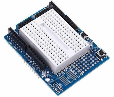
Arduino standard shield with protoboard
EDT Display
For this blog post, we will control one LED through a user interface implemented by Electron and created in HTML with Node.js, CSS and JavaScript support to access the hardware. To make this possible, we verified which Colibri i.MX 6 modules can connect to the Aster carrier board. We decided to use GPIO 35, physically connecting one cable to the SODIMM_133 output pin (connected to GPIO 35) and using it to control an LED on a protoboard. To see the other module pins, visit this site.
Electron Install
We installed Linux XY with Toradex Easy Installer. Next, we’ll install the Electron framework according to the steps in this article.
First, we need to update the system packages and install a few additional packages and libraries. To do this, run the following commands in the module’s terminal:
opkg update opkg install libxss1 libcups2 nodejs nodejs-npm git
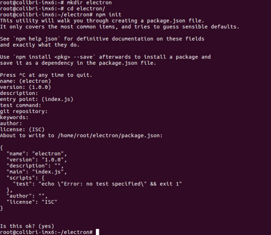
Next, run the command npm init inside a directory called electron to create the package.json file, which will be the repository for the following installation. In this step, press the Return key to accept the standard configuration:
mkdir electron cd electron npm init
You’ll see something like the following output as you press Return:
name: (electron) version: (1.0.0) description: entry point: (index.js) test command: git repository: keywords: author: license: (ISC) About to write to /home/root/electron/package.json: { "name": "electron", "version": "1.0.0", "description": "", "main": "index.js", "scripts": { "test": "echo \"Error: no test specified\" && exit 1" }, "author": "", "license": "ISC" }
Lastly, install the pre-built Electron package:
npm install electron-prebuilt
Demonstration
Below is a video that shows some GUIs created with Electron running on a Colibri IMX6 module.
youtube
There are a couple of examples which you can easily download and test.
Start by downloading the sample repository to a new directory:
mkdir Samples cd Samples git clone https://github.com/hokein/electron-sample-apps.git
To execute a sample, change your working directory to the project’s and execute the command below. As an example, we’ll run the “Frameless-Window” GUI, one of the samples from the video above:
cd electron-sample-apps cd frameless-window ~/electron/node_modules/.bin/electron .
You can find many more example GUIs created for Electron online.
Next, we’ll take a quick look at an interface that isn’t in the samples downloaded above. This GUI implements the interaction shown on the site below this screenshot, in which text boxes can be moved using a drag-and-drop action.

https://bevacqua.github.io/dragula/
Development
Electron requires four basic files. The first, package.json, was created during the install. It will be used to start the Electron application by running main.js. main.js will initialize the GUI and load index.html, which contains the interface’s visual components. It is connected to two other files: index.js, which contains commands to control the LED; and mystyle.css, which defines the appearance of the interface elements. We’ll begin by creating index.html inside the electron directory. This file will contain the page’s visual components, including text and images. The contents of index.html are presented below:
<!DOCTYPE html> <head> <title>Toradex Demo</title> <link href="mystyle.css" rel="stylesheet"> <script type="text/javascript" src="index.js"></script> </head> <body> <h1>Hello World!</h1> <input type="button" class="button" onclick="toogle();" value="Switch LED" /> </body> </html>
Next, we’ll create index.js, which will contain functions to turn the LED on and off. index.js uses JavaScript, and its contents are presented below:
var x; var fs = require('fs'); function set() { fs.writeFile('/sys/class/gpio/export', 35, function(err) { if (err) { console.log(err); } else { fs.writeFile('/sys/class/gpio/gpio35/direction', "out", function(err) { if (err) { console.log(err) }; }); } }); } function toogle() { if (x === 1) { x = 0; fs.writeFile('/sys/class/gpio/gpio35/value', 0); } else { x = 1; fs.writeFile('/sys/class/gpio/gpio35/value', 1); } } // initialization set(); console.log("Hello World")
After that, we’ll create main.js. This file is responsible for initializing the graphical interface and defining its resolution. The contents of main.js are presented below:
const electron = require('electron') const {app, BrowserWindow} = electron app.on('ready', () => { let win = new BrowserWindow({width:1280, height: 720}) win.setFullScreen(true) win.loadURL(`file://${__dirname}/index.html`) })
After that, we’ll create mystyle.css, which defines the appearance of the interface elements. The contents of mystyle.css are presented below:
body { background-color: #222930; } h1 { color: #E9E9E9; text-align: center; } .button { margin-left: 43%; margin-right: 37%; background: #93c5e6; background-image: -webkit-linear-gradient(top, #93c5e6, #6eb4e0); background-image: -moz-linear-gradient(top, #93c5e6, #6eb4e0); background-image: -ms-linear-gradient(top, #93c5e6, #6eb4e0); background-image: -o-linear-gradient(top, #93c5e6, #6eb4e0); background-image: linear-gradient(to bottom, #93c5e6, #6eb4e0); -webkit-border-radius: 60; -moz-border-radius: 60; border-radius: 60px; font-family: Arial; color: #000000; font-size: 20px; padding: 30px 30px 30px 30px; text-decoration: none; }
Note: To quickly create a new button style, you can use the tool available on this site. Next, in the package.json file, we need to modify the start script like this:
"scripts": { "start": "electron main.js" },
After creating the files, the folder should look like this:
Finally, we can run our GUI with the following command:
npm start
youtube
When we click the “Switch LED” button, the LED in the SODIMM_133 output will turn on. After clicking the button again, it will turn off. Its state will change each time we click the button.
Conclusion
In this blog post, you learned how to install the Electron software and some samples, as well as how to create an Electron GUI from scratch. This article serves as a starting point for creating graphical user interfaces for all Toradex modules. Those who are already familiar to some extent with coding for the web should find Electron very easy to use.
#Electron software#Embedded Linux#Graphical User Interface#GUI#HTML#CSS#JavaScript#NXP i.MX6#System on Module
0 notes
Text
Considerations on usage of Computer on Modules for Applications inside Emergency Response Vehicles
In this guest blog post, Diamond Systems explains considerations to use Computer Modules for an application inside an emergency response vehicle. Diamond Systems is a valued member of the Toradex Partner Network providing off-the-shelf ready-to-use Carrier Boards for Toradex Modules.
For almost three decades, Diamond Systems has developed rugged embedded computing solutions in a broad range of applications. This experience, matched with the increased popularity in CoMs (Computer on Modules) is providing innovative ways of meeting our customers’ application needs. An example of this is a recent customer Diamond worked with in Italy on a unique embedded solution that revealed great insights into why CoM-based solutions are so effective.
Access to data is critical for first responders, especially so with up-to-the-minute traffic data, GPS location and mapping, wireless internet, and access to still and video image capture, all needed within a vehicle. Such was the need of an Italian municipality requiring a cost-effective, rugged embedded computing platform with long-life and scalability for its emergency response vehicles.

Emergency Response Vehicles
The solution had to be small, high performance, consume little power, be rugged enough to withstand shock and vibration from moving vehicles, and meet the industrial operating temperature range of -40oC up to 85oC . Moreover, the platform had to provide multiple video output support for multiple configurations for the vehicles which would be using a variety of in-dash display types to access data.
Long Life
A key driver of any embedded computer’s lifespan is the life expectancy of the processor. For this reason, a CoM-based SBC is an ideal choice for a long-life solution. Since CoMs provide near-identical functionality in identical physical configurations, an obsolete processor can easily be replaced with a new one to extend the product’s lifetime, often with the added benefits of improved performance, lower cost, and/or lower power consumption. In order to realize this benefit, a CoM form factor must be selected that offers multiple options of long-life processors or which enjoys the long-term commitment of participating vendors. The Toradex Apalis form factor meets both of these requirements.
Flexible Solution
The availability of multiple processor modules also gives a CoM-based SBC great configuration flexibility, enabling it to serve a wider range of application needs. Selecting a CoM-based SBC enabled the customer to employ a solution that effectively met their computing needs and cost requirements for a variety of vehicles and applications. In this case, the solution included a Diamond Systems Eaglet CoM baseboard coupled with Toradex Apalis ARM® CoMs. The Eaglet baseboard is equipped with 4 analog inputs, 4 PWM, 8 GPIO, PCIe MiniCard socket and a micro SD socket in a compact form factor of 4.0” x 4.0” (102mm x 102mm). Eaglet’s versatile VGA, HDMI, and dual channel LVDS display options further increased the flexibility of the platform to support a wide range of in-dash display options.
Toradex’s Apalis ARM modules are available in a variety of processor/performance/memory capacity options, allowing the customer the ability to tailor the performance and cost of each configuration to each new project.
For our customer, the two-board combination of a baseboard and an ARM-based CoM provided a flexible, off-the-shelf, scalable, long-life complete embedded system that provided a variety of standard and industrial I/O features. Diamond also provided an off-the-shelf embedded Linux distribution for the product that includes all the extensions needed to support the full range of I/O features on the baseboard.
Diamond Systems’ Eaglet with Toradex Apalis iMX6 mounted The Scalable Apalis Family
Eaglet supports the Apalis iMX6, Apalis T30 and the Apalis TK1 Toradex family of modules. The Apalis form factor, as well as all processors used on the modules, have long life commitments from their suppliers, ensuring long life availability of the complete product. The Italian municipality described in this application used the Apalis iMX6 with a NXP®/Freescale i.MX 6 Quad core Cortex-A9 ARM CPU with a processor that runs at 1.0GHz, has 2GB RAM, Gigabit Ethernet Port, 4 Serial Ports and 12C, and SPI in addition to many other features and a guaranteed long life through 2028.
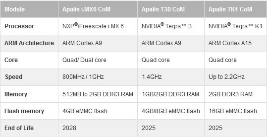
With three different modules to choose from, selecting the one that best meets the requirements is not a task. The table below shows the highlights of each module. Toradex’s pin-out is the same for each of the three Apalis CoMs, allowing them to be changed out for a system upgrade, or to extend the lifespan if needed.
While this application did not require custom options, Eaglet is highly customizable with options such as a hardwired configuration (no jumpers) and conformal coating. A low-cost expansion socket with I2C and SPI interfaces enables the addition of Diamond or customer-designed low-cost, custom I/O modules to add A/D, GPIO, and other I/O features to the board.
Results
The compact Eaglet and Apalis iMX6 ARM SBC readily met the needs of the first responder vehicles and provided the rugged (shock-resistant and demanding operating temperature), compact, low power and cost-effective solution this customer needed, yet the scalability this solution affords could easily be extended to a wide range of applications.


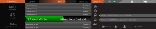
The Eaglet SBC provides municipal vehicles with a means of sharing important data including a variety of displays as seen above. In some cases, displays show information relevant to first responders’ immediate location via cameras, with GPS mapping, to assist in showing what other safety vehicles are nearby for backup, or for showing when the next train comes into the station.
#Computer on Modules#Diamond Systems#Emergency Response Vehicles#Eaglet CoM baseboard#Apalis ARM Modules#Eaglet SBC
0 notes
Text
Customizable Embedded 3D Surround View Turn-Key Solution on Apalis iMX6 SoM
Multi-Camera 3D Surround View systems are already established in many passenger vehicles. Demand for such systems now also grows for special vehicles like construction machines, harvesters, buses or military vehicles. In comparison to personal cars, these vehicles are produced in a rather moderate volume and have a high need for customization of the optical system.
In this blog post, we present a customizable 3D Surround View Turn-Key solution based on the Toradex Apalis iMX6 SoM based on the NXP® i.MX 6 SoC, that can be quickly adapted concerning the specific requirements of the targeted vehicle.
Please watch this video from Embedded World 2017 in Nuremberg, Germany, where this system solution was presented:
youtube
We also explain how to get familiar with the topic of 3D surround view, evaluating the solution via a step-by-step approach and finally how to come to a product meeting your specific needs.
TES 3D Surround View Stitching Library – the heart of the system solution
TES Electronic Solutions provides a 3D Surround View software library designed for embedded systems, CPU/GPU independency, and high customizability. Detailed information can be found on the TES 3D Surround View Website.
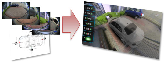
The library takes raw fish-eye pictures from memory and computes a 3D View of the vehicle in its maneuver situation.
TES 3D Surround View Highlights:
Increases safety and comfort through improved situation awareness:
Excellent stitching and 3D scene generation
Watch your maneuver situation from any position outside or inside the vehicle
Any number of predefined viewing positions (“Views”) possible with animated transitions between different views
Many parameters configurable per “View”
Highly customizable and portable
Independent from the used type of cameras (the software expects raw fish-eye pictures in memory)
3D Surround View Turn-Key Solution
In the following, we present a complete HW/SW system solution based on the Toradex Apalis iMX6Q IT Module allowing easy hardware customization to meet specific customer demands.
System Setup
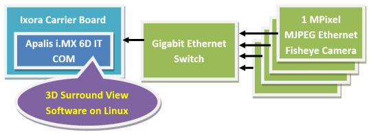
The System setup consists of the following components: Processor:
Toradex Apalis iMX6 IT Computer On Module with Heatsink
Toradex Ixora Carrier Board
Camera System:
First Sensor Mobility Area View Kit – DC–AVK including
4x 1MPixel MJPEG Ethernet Cameras (PoE), DC3K-1-EAP
4x 5m Ethernet cables (up to 25m possible for each camera)
Micrel Gigabit Ethernet (PoE) Switch
Metal Plate for Desktop Application, additionally 4 Vacuum cups for vehicle application included
Software:
TES 3D Surround View Software under Linux on Apalis iMX6
Resource Usage:
The 3D Surround View algorithm mainly exploits the GPU. The CPU is only used for system control and in the case of view-changes.
Configuration: 4 MJPEG IP cameras, combined 80Mbit data rate @30 fps and 1Mpx resolution. Low polygon car model, 1280x1024 screen resolution at 60Hz refresh rate.
GPU: 3-6 GFlops (proportional to pixel amount depicted on screen)
RAM usage: 60 MB in total
4* 10 MB for camera data buffers
2 MB for 3D environment and car model
18 MB for camera video textures
This turn-key system solution can be rapidly reproduced for evaluation and prototyping purposes. Of course, also the separate components can be exchanged or adapted to the target application needs, e.g.:
The cameras can be exchanged against other types.
A dedicated application specific main board can be designed taking the Ixora Carrier board as a reference.
The user interface and HMI overlay of the 3D Surround View software can be easily adjusted.
The 3D model of the vehicles can be easily exchanged.
Both Toradex and TES, are open to provide the necessary support. Getting started and familiar with 3D Surround View 3D Surround View is not only a topic of running an algorithm on an embedded platform and be done with it. There are many aspects of the system setup that need to be considered and require customization for specific use cases, e.g.:
Selection of the appropriate cameras regarding lens, resolution, physical data transmission (cable length!), power supply, number of cameras etc.
Positioning of the cameras (usually the higher the better)
Defining the appropriate viewing positions, i.e. virtual position and viewing vector of the “observer” in the 3D scene
Optimizing the 3D Surround View parameters, e.g. Environmental model (shape and size of the projection bowl), stitching method and parameters.
User interface for the 3D Surround View System
3D Model of the vehicle, potentially with transparency.
Just consider an excavator compared to a personal car: On an excavator, you need significantly longer cables to the cameras, the cameras are mounted typically much higher. Latency is not that much of a concern as the driving speed is lower and maybe you just want to apply only 3 cameras or mount the cameras un-symmetrically because the driver can see the left front part of his vehicle very well while he cannot see the right front part at all.
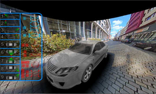
So it might be a good idea to first “play” with a 3D Surround View system to get an idea of such application aspects. For this purpose or for those who just want to give the TES software a try there is an offline PC demonstrator available at zero cost. TES provides this demonstrator on request in a zip archive with no need of installation (just unpack). Any modern Windows PC should be sufficient to run this software. The program comes with prerecorded MJPEG Ethernet streams in *.PCAP-format and runs these streams through the TES 3D Surround View software. The PC keyboard and mouse can be used to change the viewer position: predefined views are available on the number keys and “free-flight” is possible via mouse and (Shift-) arrow keys. Also, some of the 3D Surround View system parameters like the bowl-size and -shape as well as the stitching parameters can be adjusted. Do not hesitate to get in touch with TES (coordinates below) to get this Software.
First steps in the Lab and on the vehicle
Now that you have played with the software (and assuming it does more or less what you need) you might want to give it a try with real-life cameras, either in lab conditions or right away on the vehicle.
The fastest way to do that is to get a “First Sensor Mobility Area View Kit – DC–AVK” (contents see above under “System Setup”) and the TES 3D Surround View Windows PC Software in Online-Mode (Evaluation Version). This kit allows lab setups as well as on-vehicle installation using a Windows Laptop. Up to 20m cable length (between cameras and switch) has been tested so far. Also here TES can assist you in purchasing this setup.
And now on the embedded hardware…
Having tested the system under lab conditions and on the vehicle that target platform aspects now get focus (again). I.e. you want to see your setup running on the potential target hardware. At that point, you may want to take your Apalis iMX6 module with Ixora carrier board (or buy some from Toradex if you do not have those, yet) and get the TES 3D Surround View software for that target platform (prototype version). I.e. you get rid of the PC and use the Apalis/Ixora platform instead. The TES prototype software for that target platform has the same functionality as the evaluation version for PC and you can re-use the configurations that you have setup at the earlier stage now on the target.
Getting to a product
For a product, you now have to customize the system to meet your specific application requirements. I.e. you use the Apalis iMX6 module as core and might re-design the carrier board based on the Ixora design data to meet your specific requirements regarding, interfaces, power supply, mechanics etc.
In that step or even before you also may want to exchange the cameras with other types.
Again, TES can assist you also in the hardware and system customization, development and (if wanted) manufacturing process.
Summary
We have introduced an embedded 3D Surround View Turn-Key Solution and explained a process to get you familiar with this topic starting at zero cost. Following this process, your product development risk is significantly reduced because you can evaluate the system in a step-by-step approach and at the same time determine your application specific requirements. Finally, we have introduced the steps to come to a product based on this turn-key solution. Just get started
#Apalis iMX6 SoM#3D Surround View#Turn-Key Solution#toradex modules#System on Modules#Computer on Modules
0 notes
Video
youtube
Some applications have specific requirements for a system’s boot time. Often the system does not need to be immediately ready for all its tasks, but it should be ready for certain mission-critical tasks (e.g. accepting commands over Ethernet or displaying a user interface). Read our blog to understand the various methodologies and measures for improving the Embedded Linux Boot Time on Toradex's System on Modules. https://www.toradex.com/blog/embedded-linux-boot-time-optimization
#Embedded Linux Boot#Boot Time Optimization#Toradex System on Modules#Computer on Modules#Toradex Blog
0 notes
Last Seen Blogs


earth-7103984
Earth-7103984

anhsexviet
Untitled

dotsdigital
This Is.. Emotional Buisness

itsareactiontosmut
It's a reaction.