#Metalwork Cylinders
Text
Discover the Hidden Secret Behind the Explosive Performance of Shinano Pneumatic Tools

Are you searching for top-notch air tools that deliver exceptional performance? Look no further! In this post, we unveil the hidden secret behind the explosive performance of Shinano Pneumatic Tools. Whether you're a DIY enthusiast or a professional in need of reliable tools, Shinano has got you covered. From the impressive Shinano High Speed Grinder to the efficient Shinano Air Polishers Tools, and the precise Shinano Pneumatic Screwdriver, we've got the scoop on these remarkable tools that have taken the market by storm.
Unveiling the Shinano High Speed Grinder
When it comes to heavy-duty grinding, the Shinano High Speed Grinder stands in a league of its own. Its robust design, coupled with high-speed capabilities, ensures swift material removal with utmost precision. Whether you're working with metal, wood, or other materials, this grinder's performance is truly explosive. Say goodbye to time-consuming grinding tasks and hello to efficiency and excellence.
Masterful Performance with Shinano Air Polishers Tools
Achieving a flawless finish is an art, and Shinano Air Polishers Tools are the brushes of the modern artisan. These tools combine ergonomic design with powerful pneumatic technology to give your surfaces a stunning, polished look. From automotive enthusiasts to woodworking professionals, these air polishers elevate your work to the next level. Unleash your creativity and achieve results that speak for themselves.
The Precision of Shinano Pneumatic Screwdriver
When it comes to assembling intricate machinery or working with delicate components, precision is non-negotiable. The Shinano Pneumatic Screwdriver offers the accuracy and control you need to fasten screws seamlessly. Its ergonomic grip reduces fatigue, ensuring prolonged productivity without compromising on performance. Say goodbye to stripped screws and inefficient work – Shinano's screwdriver is here to redefine your working experience.
Buy Air Tools Online UK - Your Gateway to Excellence
Are you based in the UK and in need of top-quality air tools? Look no further than Pneutube Limited's impressive selection. From the explosive performance of Shinano Pneumatic Tools to the convenience of shopping online, Pneutube Limited brings you the tools you need with just a few clicks. Don't settle for subpar tools; elevate your craftsmanship with the best.
FAQs
Q: Can these tools be used by beginners?
A: Absolutely! Shinano Pneumatic Tools are designed to cater to both beginners and professionals, ensuring ease of use without compromising performance.
Q: Are replacement parts easily available?
A: Yes, Pneutube Limited offers a wide range of replacement parts for Shinano tools, ensuring your investment is a long-lasting one.
Conclusion
In conclusion, the explosive performance of Shinano Pneumatic Tools is not just a myth – it's a reality that countless professionals and enthusiasts swear by. From the Shinano High Speed Grinder's robust grinding capabilities to the finesse of Shinano Air Polishers Tools and the precision of the Shinano Pneumatic Screwdriver, these tools redefine excellence. So why wait? Elevate your work by embracing the hidden secret behind Shinano's remarkable performance. Visit Pneutube Limited today and buy air tools online in the UK to embark on a journey of craftsmanship like never before. Your projects deserve nothing less than the best, and Shinano delivers precisely that.
#Shinano Pneumatic Tools#Shinano Pneumatic#Air Tool Parts & Accessories#Buy Air Tools Online UK#Online Cutter Standard UK#Online Standard Die Grinders UK#Shinano Pneumatic Drills#Pneumatic Impact Wrench Tools#Buy Pneumatic Air Polishers Tools#Buy Shinano Pneumatic Screwdriver#Buy Flexible Nylon Tube Online#Online Gas Springs Tools#VariLift Gas Spring#Buy Pneumatic Equipment#Pneumatic Equipment Online#Metalwork Valves#Festo Valves#Metalwork Push Fittings#Festo Cylinders#Metalwork Pneumatics#Metalwork Cylinders#Festo Push Fittings#Shinano Air Tools UK#Shinano Ratchet Wrench Tools Online#Shinano Air Sanders Tools#Shinano High Speed Grinder#Buy Shinano Air Tools Online UK
2 notes
·
View notes
Text

1958 Porsche 356 A Coupe
The Porsche 356A (T2) Speedster September 1957 to August 1958 (Carrerra Speedsters continued into 1959)
The last of the 356A Speedsters are probably the most attractive and the most desirable. The 356A (T2) Speedster was introduced in September 1957 and continued until the basic Speedster was replaced by the Convertible D in August 1958 although a number of Carrera, GS and GT Speedsters were produced in 1959.
History:
Ferdinand Porsche and the foundation of the Porsche Company
Ferdinand Porsche was born on September 3rd 1875, in the Bohemian village of Maffersdor. After attending grammar school and Staatsgewerbeschule (State Vocational School) in Reichenberg, he entered his father's metalworking business. The young and imaginative Ferdinand pursued a fascination with electricity working on the design of an electric car and in 1900 The Lohner-Porsche electric car is presented at the World Fair in Paris. Porsche's wheel hub engines brought the young engineer international attention. In the same year, he developed an all-wheel-drive racecar, as well as a hybrid petrol/electric vehicle.
In 1906 Ferdinand Porsche became Technical Director at Austro-Daimler in Wiener Neustadt. At the age of only 31, he became responsible for the model range of one of Europe's largest automotive concerns.
In September1909 Ferdinand's first son, Ferdinand Anton Ernst Porsche, later known as 'Ferry', was born. In 1910 The Austro-Daimler touring car designed by Ferdinand Porsche scores a triple victory in the Prince Henry Trials.
In 1923 as Technical Director and Board Member of the Daimler-Motoren-Gesellschaft in Stuttgart, Ferdinand Porsche was responsible for the design of the legendary Mercedes Compressor Sports Car and in the following year, he led the development of the 2-litre racecar won the Targa Florio. The Mercedes-Benz S-Type models dominate international motorsport from 1927.
Professor Ferdinand Porsche 1875-1951
In 1931 Ferdinand Porsche founded the company that bears his name "Dr. Ing. h. c. F. Porsche GmbH" to provide 'engineering and consultation on engine and vehicle design'. Based in Stuttgart the company carried out projects for manufacturers such as as Wanderer, Zündapp and NSU. In 1933 Porsche developed a Grand Prix mid-engined 16-cylinder racecar for Auto Union. He also developed a rear engined compact vehicle concept for NSU.
One year later the Porsche company received an official order for the design and construction of a German 'Peoples Car' or Volkswagen. The prototype was developed and assembled in the garage of the Porsche villa in Stuttgart and was road tested within 12 months At the same time production facilities were being set up for the Volkswagen which was officially called the 'KdF-Wagen'.
In December 1935 Ferdinand Alexander Porsche the first son of Ferry Porsche (and later known as 'Butzi') was born in Stuttgart.
During 1939 Porsche developed 3 racing coupés for long-distance endurance competition. These 'BerlinRome-Wagens' could be considered the forerunners of later Porsche sports cars.
He also designed the Mercedes T-80 in1939 to conquer the world land speed record. It was reputed to have a 3000 hp aircraft engine.
Because of the outbreak of the second world war Volkswagen production was diverted towards the military version of the Beetle, the Kübelwagen and Schwimmwagen. Only 1207 Volkswagen KdFs were built between 1941 and 1944
Porsche also designed several heavy tanks but did not get the production contract. Towards the end of the war the Porsche Engineering office moved to the relative safety of Gmünd in the Austrian province of Carinthia.
After the war the Volkswagen factory at Wolfsburg was taken over by the British and Ferdinand Porsche was arrested and imprisoned in France for 20 months.
In 1946 under the direction of Ferdinand Porsche's son Ferry, the Porsche Engineering office became involved in the design of an all-wheeldrive Grand Prix racecar for an Italian industrialist, Piero Dusio.
Ferry Porsche saw a market for a small, light two seater roadster and was unable to find a car in the market that matched his preference. He decided to build a car which became the first 356 and the first sportscar to bear the Porsche name.
4 notes
·
View notes
Text
THE ULTIMATE GUIDE TO PRESSES, SHEARS, LASER CUTTERS AND PUNCHES
In the world of metal fabrication, several key machines play a vital role in shaping and cutting metal with precision and efficiency. This ultimate guide provides comprehensive knowledge and insights into the essential products of the industry: Press Brake, Press Brake Tools, Shearing Machine, Laser Cutting Machine, and Power Press. Whether you are a beginner or an experienced professional, this guide will equip you with the necessary information to understand, select, and optimize the use of these machines for your metalworking needs.
Press Brake:
1.What is a Press Brake?
A press brake is a key equipment used in the field of metal fabrication for bending and folding metal sheets. It utilizes pressure to bend the metal sheet into the desired shape. It is commonly used to create bent parts, enclosures, tubing, and other metal components.
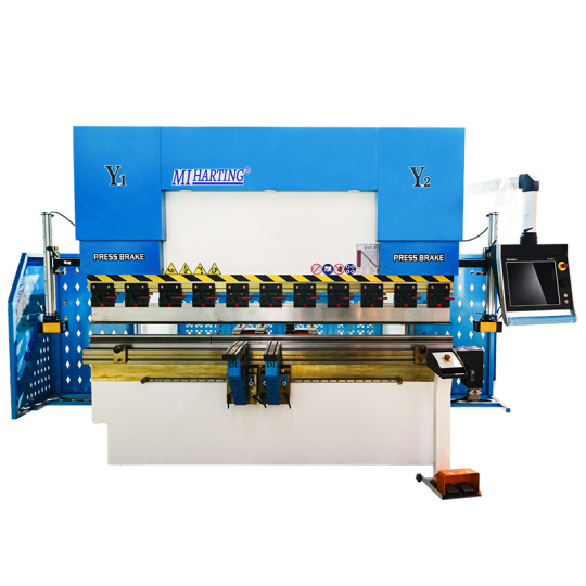
A press brake consists of an upper die and a lower die, with the upper die fixed to the frame and the lower die movable through a hydraulic system or mechanical drive system. The metal sheet is placed between the two dies and then bent into the desired angle and shape by applying pressure.
Press brakes typically have the following features and capabilities:
(1)Bending capacity: Press brakes can achieve bends at different angles and radii to meet various workpiece requirements.
(2)Precision: High precision bending results can be achieved by adjusting the position of the upper and lower dies.
(3)Automation: Some modern press brakes are equipped with CNC systems, allowing for automated operation and programming.
(4)Versatility: Press brakes can be used for various bending tasks and different types of metal materials by changing different tools and dies.
(5)Safety: Press brakes are typically equipped with safety devices such as light curtains, protective covers, and emergency stop buttons to ensure operator safety.
Press brakes are widely used in industries such as automotive manufacturing, aerospace, construction, electronics, and more. They are essential equipment for achieving precise and efficient metal fabrication.
2.Types of Press Brakes
There are several types of press brakes commonly used in metal fabrication:
Mechanical Press Brake: Uses a mechanical flywheel and clutch system for bending.
Hydraulic Press Brake: Utilizes hydraulic cylinders for precise bending control.
Servo-Electric Press Brake: Uses electric servo motors for high precision bending.
Pneumatic Press Brake: Relies on compressed air for lighter applications.
CNC Press Brake: Equipped with computerized controls for automated and precise bending operations.
The choice of press brake depends on factors such as material type, thickness, bending requirements, and production volume.
3.Components and Working Principles
A press brake consists of several key components that work together to perform the bending operation. Here are the main components and their functions:
Frame: The frame provides structural support and stability to the press brake.
Bed: The bed is a flat surface where the material to be bent is placed.
Ram: The ram is the moving part of the press brake that applies force to the material for bending.
Die: The die is a tool that shapes the material by providing a specific bending angle.
Punch: The punch is another tool that presses against the material, working in conjunction with the die to bend it.
Backgauge : The backgauge is an adjustable device that positions the material accurately for consistent bending.
4.Key Features and Benefits
Material Placement: The operator places the metal sheet or plate on the bed of the press brake.
Tool Setup: The appropriate die and punch are selected and installed on the press brake.
Backgauge Adjustment: The backgauge is adjusted to position the material correctly for the desired bend.
Bending Process: The ram moves downward, applying force to the material, which is sandwiched between the punch and the die. This bending action creates the desired angle in the material.
Material Removal: Once the bending is complete, the operator removes the bent material from the press brake.
5.Applications and Industries
Press brakes are widely used in various industries for different applications, including:
Metal Fabrication: Press brakes are commonly used in metal fabrication shops to bend and shape metal sheets and plates for various products such as enclosures, brackets, frames, and panels.
Automotive Industry: Press brakes are used in the automotive industry for manufacturing components like chassis, brackets, and body panels.
Aerospace Industry: Press brakes are utilized in the aerospace industry for bending and forming metal parts used in aircraft structures and components.
Construction and Architecture: Press brakes are used in the construction and architectural sectors for bending metal components used in building structures, facades, and decorative elements.
Electronics and Appliances: Press brakes are employed in the manufacturing of electronic enclosures, appliance components, and consumer products.
Press Brake Tools:
1.Importance of Press Brake Tools
Press brake tools play a crucial role in the performance and efficiency of press brake machines. Here are some key points highlighting the importance of press brake tools:
(1) Precision Bending: Press brake tools are designed to provide precise and accurate bending angles. They ensure consistent results and help meet the required specifications for the final product. The quality and precision of the tools directly impact the overall quality of the bent parts.
(2) Versatility: Press brake tools come in various shapes, sizes, and configurations to accommodate different bending requirements. They can be customized or interchanged to achieve different bending angles, radii, or complex shapes. This versatility allows manufacturers to produce a wide range of products using the same machine.
(3) Durability and Longevity: Press brake tools are made from high-quality materials such as hardened steel or special alloys, which make them highly durable and resistant to wear and tear. Proper maintenance and regular tool inspections ensure their longevity, reducing the need for frequent replacements.
(4) Efficiency and Productivity: Well-designed press brake tools optimize the bending process, reducing setup time, and increasing productivity. They enable faster bending cycles, allowing manufacturers to produce more parts in less time. Efficient tooling also minimizes material waste and improves overall production efficiency.
(5) Cost Savings: Using the right press brake tools can lead to cost savings in multiple ways. Accurate bending reduces material waste, saving on raw material costs. Efficient tooling reduces setup time and increases machine productivity, maximizing the output per hour. Additionally, durable tools have a longer lifespan, reducing the frequency of replacements and maintenance costs.
(6) Safety: Press brake tools are designed with safety features in mind. They provide proper clamping and holding mechanisms to secure the material during bending, minimizing the risk of accidents. Additionally, using high-quality tools reduces the chances of tool failure or breakage, ensuring operator safety.
(7) In summary, press brake tools are vital for achieving precise and accurate bending results, improving productivity, reducing costs, and ensuring operator safety. Selecting the right tools and maintaining them properly is essential for the efficient operation of press brake machines.

2.Types of Press Brake Tools (including ARC Press Brake Tools)
There are several types of press brake tools available, each designed for specific bending applications. Here are some common types of press brake tools:
V-Die: V-dies are the most commonly used press brake tools. They consist of a bottom die with a V-shaped groove and a punch with a matching V-shaped tip. V-dies are versatile and can be used for a wide range of bending angles and materials.
(1) Bottoming Die: Bottoming dies, also known as flat dies, have a flat surface instead of a V-shaped groove. They are used for achieving sharp bends or bending thicker materials where a tighter radius is required.
(2) Gooseneck Punch: Gooseneck punches have a curved shape that allows for deep and offset bends. They are commonly used for bending channels, boxes, and other complex shapes.
(3) Hemming Tool: Hemming tools are used for creating hems or flanges on the edge of a sheet metal part. They consist of a punch and die set that folds the material over itself to create a secure edge.
(4) Radius Tool: Radius tools, also known as radius punches or radius dies, are used for creating curved bends with a specific radius. They are available in various sizes to accommodate different bending requirements.
(5) Multi-V Die: Multi-V dies have multiple V-shaped grooves of different sizes on a single die. They allow for quick and easy tool changes without the need for separate dies for different bending angles.
(6) ARC Press Brake Tools: ARC press brake tools are specialized tools used for bending sheet metal into arc shapes. They are designed to create precise and consistent curved bends, commonly used in applications such as cylindrical parts, tubes, or curved profiles.
ARC press brake tools typically consist of a bottom die with a curved groove and a punch with a matching curved tip. They enable the accurate and repeatable bending of sheet metal into various arc shapes.
3.Material Selection and Coatings
When it comes to press brake tools, material selection and coatings play an important role in their performance and longevity. Here's a brief overview of material selection and coatings for press brake tools:
Material Selection:
(1) Tool Steel: Tool steel, such as D2 or A2, is commonly used for press brake tools due to its high hardness, wear resistance, and toughness.
(2) Carbide: Carbide inserts or tips are used for heavy-duty applications or when bending abrasive materials. Carbide provides excellent wear resistance but is more brittle than tool steel.
(3) High-Speed Steel (HSS): HSS is another option for press brake tools. It offers good toughness and wear resistance, but not as high as tool steel.
Coatings:
(4) Nitride Coating: Nitride coatings, such as TiN (Titanium Nitride) or TiCN (Titanium Carbonitride), improve the surface hardness and wear resistance of the tool. They are suitable for general-purpose bending applications.
(5) DLC Coating: DLC (Diamond-Like Carbon) coatings provide excellent hardness, low friction, and high wear resistance. They are ideal for bending stainless steel and other difficult-to-form materials.
(6) PVD Coating: Physical Vapor Deposition (PVD) coatings, like TiAlN (Titanium Aluminum Nitride), enhance the tool's performance by reducing friction and increasing wear resistance.
(7) Chrome Plating: Chrome plating is a common coating for press brake tools. It provides good corrosion resistance and reduces friction during bending operations.
The selection of material and coating depends on factors such as the type of material being bent, the bending application, and the desired tool life. It's important to choose the right combination of material and coating to ensure optimal performance and durability of the press brake tools.
4.Tooling Configurations and Considerations
When it comes to press brake tools, the tooling configurations and considerations are crucial for achieving accurate and efficient bending operations. Here are some important aspects to consider:
Tooling Configurations:
(1) V-Die: The V-die is the female tool that provides the desired bend shape. It comes in various widths and angles to accommodate different material thicknesses and bending requirements.
(2) Punch: The punch is the male tool that contacts the material and applies force to create the bend. It also comes in different shapes and sizes to achieve specific bend angles and radii.
(3) Multi-V Die: Multi-V dies have multiple V-shaped grooves of different widths and angles. They allow for bending different material thicknesses and angles without changing the die.
(4) Gooseneck Punch: Gooseneck punches have a curved shape that allows for deep or offset bends where space is limited.
(5) Hemming Tools: Hemming tools are used for creating hemmed edges or flanges on sheet metal.
Considerations:
(1) Material Thickness: The tooling configuration should be selected based on the material thickness being bent. Thicker materials may require larger tooling to accommodate the increased force and prevent tool damage.
(2) Material Type: Different materials have varying properties, such as hardness and ductility, which can affect the tooling selection. Harder materials may require tougher tooling materials or coatings.
(3) Bend Angle and Radius: The desired bend angle and radius dictate the selection of punch and die configurations. Sharp bends require smaller punch radii, while larger radii are needed for gentler bends.
(4) Tooling Alignment: Proper alignment between the punch and die is essential for achieving accurate and consistent bends. Misalignment can result in uneven bends or tool damage.
(5) Tooling Maintenance: Regular inspection and maintenance of the tooling are necessary to ensure optimal performance and longevity. This includes cleaning, lubrication, and replacement of worn-out components.
By considering the tooling configurations and these important factors, you can select the appropriate press brake tools for your specific bending requirements. This will help you achieve precise and efficient bending operations while prolonging the tooling life.
5.Tool Maintenance and Longevity
(1) Regular cleaning: Clean the press brake tools regularly to remove debris, dirt, and metal shavings. Use appropriate cleaning agents and tools to avoid damaging the tool surfaces. Ensure that the tools are completely dry before storing them.
(2) Lubrication: Apply lubrication to the press brake tools as recommended by the manufacturer. Lubrication helps reduce friction and wear, improving the tool's lifespan. Follow the manufacturer's guidelines for the type and frequency of lubrication.
(3) Inspection and repair: Regularly inspect the press brake tools for signs of wear, damage, or deformation. Check for any cracks, chips, or excessive wear on the cutting edges. If any issues are detected, promptly repair or replace the damaged parts to prevent further damage and ensure accurate bending results.
(4) Proper storage: Store the press brake tools in a clean and dry environment to prevent corrosion and damage. Use dedicated tool racks or boxes to keep the tools organized and protected. Avoid placing heavy objects on top of the tools to prevent deformation.
(5) Operator training: Proper training of operators is essential for tool maintenance and longevity. Educate operators on the correct usage techniques, operating limits, and safety precautions. Encourage operators to report any issues or abnormalities with the tools promptly.
By following these maintenance tips, you can extend the lifespan of your press brake tools and ensure consistent and accurate bending operations. Regular maintenance not only improves tool performance but also contributes to the overall safety and efficiency of the bending process.
6.Advanced Tooling Technologies and Innovations
Advanced tooling technologies and innovations have significantly improved the performance and capabilities of press brake tools. Here are some key advancements in press brake tooling:
(1) High-strength materials: Press brake tooling is now made from high-strength materials such as hardened steel alloys or carbide. These materials offer superior durability, wear resistance, and longer tool life compared to traditional tooling materials.
(2) Coatings and surface treatments: Advanced coatings and surface treatments, such as TiN (Titanium Nitride) or DLC (Diamond-Like Carbon), are applied to press brake tools to enhance their performance. These coatings reduce friction, improve wear resistance, and prevent material adhesion, resulting in improved bending quality and longer tool life.
(3) Precision tooling systems: Modern press brake tooling systems feature precision-ground tooling with tight tolerances. These systems ensure accurate and repeatable bending results, reducing setup times and increasing productivity.
(4) Quick-change tooling systems: Quick-change tooling systems allow for rapid tooling setup and changeovers. These systems utilize standardized tooling holders and clamping mechanisms, enabling operators to switch between different tooling setups quickly and efficiently.
(5) 3D modeling and simulation: Advanced software tools enable 3D modeling and simulation of bending processes. These tools help optimize tooling designs, simulate bending sequences, and detect potential collision or interference issues before actual production. This reduces setup time, minimizes errors, and improves overall efficiency.
(6) Custom tooling solutions: Tooling manufacturers now offer custom tooling solutions tailored to specific bending applications. These solutions include specialized tool profiles, custom tool coatings, and even tooling with integrated sensors for process monitoring and control.
These advancements in press brake tooling technologies have significantly improved productivity, accuracy, and tool life. By adopting these innovations, manufacturers can achieve higher efficiency, reduce downtime, and produce high-quality bent parts consistently.
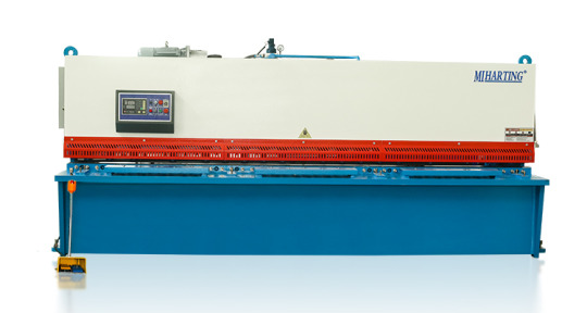
Shearing Machine:
1.Understanding Shearing Machines
Shearing machines are industrial mechanical devices used for cutting metal sheets and other materials. They apply shearing force to cut the materials into desired shapes and sizes. Shearing machines are widely used in manufacturing and metalworking industries to produce various products and components.
The working principle of shearing machines involves placing the material on a shear table and applying force through cutting blades to cause the material to fracture. Shearing machines can perform operations such as straight cutting, curved cutting, and angle cutting. Depending on the specific requirements, shearing machines can have different cutting capacities and precision.
There are various types of shearing machines, including hydraulic shearing machines, mechanical shearing machines, and manual shearing machines. Hydraulic shearing machines use hydraulic systems to provide cutting force and offer high power and precision, making them suitable for large-scale and heavy-duty cutting tasks. Mechanical shearing machines use mechanical mechanisms to provide cutting force and are typically more compact and cost-effective, suitable for medium-sized cutting tasks. Manual shearing machines require manual operation and are suitable for small-scale and simple cutting work.
The cutting capacity of shearing machines depends on their maximum cutting thickness and cutting width. Larger shearing machines generally have higher cutting capacity and can handle thicker and wider materials. The cutting precision of shearing machines is influenced by factors such as blade sharpness, adjustment of blade clearance, rigidity of the frame, and material characteristics.
Safety considerations are important when operating shearing machines. Operators should receive proper training on the operation procedures and safety precautions of shearing machines. Additionally, appropriate personal protective equipment, such as safety goggles and gloves, should be worn. Regular inspection and maintenance of shearing machines are necessary to ensure their proper functioning and safe operation. Following the operation manual and manufacturer's recommendations is crucial to ensure the safety and effectiveness of operating shearing machines.
2.Hydraulic vs. Mechanical Shearing Machines
Hydraulic and mechanical shearing machines are two common types of shearing machines used in industrial applications. Here's a comparison between the two:
Power Source:
(1) Hydraulic Shearing Machines: These machines use a hydraulic system to generate the cutting force. The force is applied through hydraulic cylinders powered by a hydraulic pump. Hydraulic shearing machines offer high power and can handle heavy-duty cutting operations.
(2) Mechanical Shearing Machines: These machines use mechanical mechanisms, such as gears, levers, and flywheels, to generate the cutting force. The force is applied directly through the mechanical components. Mechanical shearing machines are generally more compact and cost-effective.
Power and Precision:
(1) Hydraulic Shearing Machines: Due to the hydraulic system, hydraulic shearing machines can provide high cutting power. They are capable of cutting thick and hard materials with precision. The hydraulic system allows for better control and adjustment of the cutting force, resulting in accurate and consistent cuts.
(2) Mechanical Shearing Machines: Mechanical shearing machines provide a lower cutting power compared to hydraulic ones. They are suitable for medium-duty cutting tasks. However, the cutting precision of mechanical shearing machines can be affected by factors such as mechanical wear and tear, which may require more frequent adjustments and maintenance.
Size and Space:
(3) Hydraulic Shearing Machines: Hydraulic shearing machines are generally larger and require more space due to the hydraulic system components, such as the hydraulic pump, cylinders, and hoses.
(4) Mechanical Shearing Machines: Mechanical shearing machines are more compact and take up less space. They are often preferred in smaller workshops or where space is limited.
Cost:
(1) Hydraulic Shearing Machines: Hydraulic shearing machines are typically more expensive due to the complexity and cost of the hydraulic system components.
(2) Mechanical Shearing Machines: Mechanical shearing machines are generally more affordable and cost-effective.
In summary, hydraulic shearing machines provide high power and precision, making them suitable for heavy-duty cutting operations. They are larger and more expensive. On the other hand, mechanical shearing machines are more compact, cost-effective, and suitable for medium-duty cutting tasks. The choice between hydraulic and mechanical shearing machines depends on the specific cutting requirements, available space, and budget considerations.
3.Components and Operation
Components of a Shearing Machine:
(1) Shear Table: This is the flat surface or bed on which the material to be cut is placed. It provides support and stability during the cutting process.
(2) Cutting Blades: These are the sharp blades that perform the actual cutting of the material. They are typically made of high-quality tool steel and are securely mounted on the machine. The blades can be straight, curved, or angled, depending on the desired cutting operation.
(3) Blade Clearance Adjustment: Shearing machines often have a mechanism for adjusting the clearance between the upper and lower blades. This adjustment allows for precise control of the cutting gap, ensuring clean and accurate cuts.
(4) Back Gauge: The back gauge is a movable stop or fence located behind the shear table. It helps in positioning the material accurately for repetitive cutting operations. The back gauge can be manually adjusted or controlled by a motorized system.
(5) Drive System: The drive system provides the power to move the cutting blades. In hydraulic shearing machines, the drive system consists of a hydraulic pump, cylinders, and valves. In mechanical shearing machines, it typically involves mechanical components such as gears, levers, and flywheels.
(6) Control Panel: The control panel houses the controls and switches for operating the shearing machine. It allows the operator to start and stop the machine, adjust settings, and monitor the cutting process.
Operation of a Shearing Machine:
(1) Material Preparation: The material to be cut is prepared by ensuring it is clean, straight, and properly aligned with the shear table. Any protective coatings or films on the material should be removed.
(2) Material Placement: The material is placed on the shear table, ensuring it is aligned with the back gauge if applicable. The operator should take care to position the material securely and avoid any obstructions that could interfere with the cutting process.
(3) Blade Clearance Adjustment: The blade clearance is set according to the thickness and type of material being cut. This adjustment ensures proper shearing without damaging the material or the blades. The manufacturer's guidelines or machine manual should be followed for the correct blade clearance settings.
(4) Cutting Operation: Once the material is properly positioned and the blade clearance is set, the operator initiates the cutting operation. In hydraulic shearing machines, the hydraulic pump is activated to provide the necessary cutting force. In mechanical shearing machines, the operator engages the drive system, which transfers power to the cutting blades.
(5) Monitoring and Control: During the cutting process, the operator monitors the operation to ensure smooth and accurate cutting. The control panel may provide indicators or displays for monitoring the cutting speed, blade position, and other parameters. Any abnormalities or issues should be addressed promptly.
(6) Material Removal and Repeat: After the cutting operation is complete, the cut pieces are removed from the shear table. The process can be repeated for subsequent cuts, adjusting the back gauge if necessary.
It's important to note that the specific operation of a shearing machine may vary depending on the machine model and manufacturer. Operators should always refer to the machine's manual and receive proper training before operating the shearing machine.
4.Cutting Capacity and Accuracy
Cutting Capacity and Accuracy are important considerations when using a shearing machine. Let's discuss each of them:
Cutting Capacity:
(1) Shearing machines have a specified cutting capacity, which refers to the maximum thickness and width of the material that can be effectively cut. The cutting capacity is determined by factors such as the power of the machine, the strength of the blades, and the rigidity of the shear table.
(2) It is crucial to choose a shearing machine with a cutting capacity that matches the requirements of the materials you will be working with. Attempting to cut materials beyond the machine's capacity can result in poor cutting quality, blade damage, or even machine malfunction.
Cutting Accuracy:
(1) Cutting accuracy refers to the ability of the shearing machine to make precise and consistent cuts. It is influenced by several factors, including the design and condition of the machine, the sharpness and alignment of the blades, and the control and monitoring systems.
(2) To achieve high cutting accuracy, it is important to maintain the shearing machine properly. Regular blade sharpening and replacement, as well as routine maintenance and calibration, can help ensure accurate cuts.
(3) The operator's skill and experience also play a significant role in achieving cutting accuracy. Proper material positioning, adjustment of blade clearance, and careful monitoring of the cutting process are essential for obtaining precise and clean cuts.
Factors Affecting Accuracy:
(1) Blade Condition: Dull or damaged blades can lead to uneven cuts and reduced accuracy. Regular inspection and maintenance of the blades are necessary to maintain cutting precision.
(2) Blade Clearance: Incorrect blade clearance can result in distorted or incomplete cuts. It is important to set the appropriate blade clearance for the material being cut.
(3) Material Alignment: Proper alignment of the material with the shear table and back gauge is crucial for accurate cuts. Misalignment can cause crooked or uneven cuts.
(4) Machine Rigidity: The rigidity of the shearing machine, including the shear table and frame, affects cutting accuracy. A sturdy and well-maintained machine provides better stability and reduces the chances of deflection during the cutting process.
It is recommended to follow the manufacturer's guidelines and recommendations for the specific shearing machine being used. Regular maintenance, blade inspection, and operator training are essential to ensure optimal cutting capacity and accuracy.
5.Safety Considerations
Safety considerations are of utmost importance when operating a shearing machine. Here are some key safety measures to keep in mind:
(1) Read and Follow the Manual: Familiarize yourself with the manufacturer's instructions and safety guidelines provided in the machine's manual. Understand the machine's features, controls, and potential hazards before operating it.
(2) Personal Protective Equipment (PPE): Always wear appropriate PPE, including safety glasses or goggles, gloves, and ear protection. Depending on the specific machine and the materials being cut, additional protective gear such as a face shield or apron may be required.
(3) Machine Inspection: Before starting the machine, inspect it for any signs of damage, loose parts, or malfunctioning components. Ensure that all safety guards and devices are in place and functioning correctly.
(4) Training and Competence: Only trained and authorized personnel should operate a shearing machine. Proper training should cover machine operation, safety procedures, emergency shutdown, and handling of materials.
(5) Material Handling: Use caution when handling materials, especially large or heavy ones. Use lifting equipment or assistance when necessary to avoid strain or injuries.
(6) Emergency Stop: Familiarize yourself with the location and operation of the emergency stop button or switch. Be prepared to use it in case of any emergency or unsafe situation.
(7) Blade Safety: Never reach into the cutting area while the machine is in operation or attempt to adjust the blades without proper training. Always wait for the machine to come to a complete stop before making any adjustments or maintenance.
(8) Housekeeping: Maintain a clean and organized work area. Remove any debris, scraps, or obstructions that may interfere with the machine's operation or cause accidents.
(9) Lockout/Tagout: Follow proper lockout/tagout procedures when performing maintenance or repairs on the machine. This involves disconnecting the power source and ensuring that it cannot be re-energized accidentally.
(10) Regular Maintenance: Adhere to the recommended maintenance schedule for the shearing machine. This includes blade sharpening, lubrication, and inspection of mechanical and electrical components.
Remember, safety should always be the top priority when operating any machinery. If you have any concerns or encounter any issues with the shearing machine, stop the operation immediately and seek assistance from a qualified technician or supervisor.
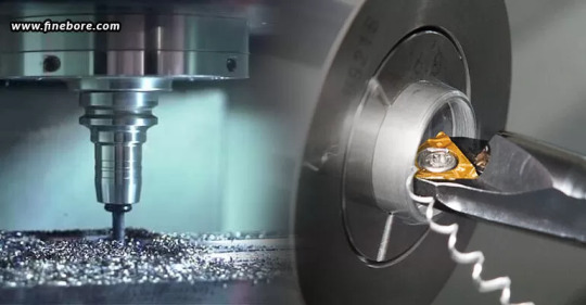
Laser Cutting Machine:
1.Introduction to Laser Cutting:
Laser cutting is a highly precise and versatile method of cutting various materials using a high-powered laser beam. It has revolutionized the manufacturing industry by providing a faster, more accurate, and more efficient alternative to traditional cutting methods. Laser cutting machines are used in a wide range of industries, including automotive, aerospace, electronics, signage, and jewelry making.

2.Types of Laser Cutting Machines:
There are different types of laser cutting machines available, each with its own advantages and suitable applications. The most common types include CO2 lasers, fiber lasers, and neodymium lasers.
CO2 lasers are the most widely used type of laser cutting machine. They use a mixture of carbon dioxide, nitrogen, and helium as the laser medium. CO2 lasers are versatile and can cut a wide range of materials, including non-metallic materials such as plastics, wood, and fabrics, as well as metals.
Fiber lasers use optical fibers as the laser medium. They are highly efficient and are primarily used for cutting metals, including stainless steel, aluminum, and copper. Fiber lasers offer high beam quality, which results in faster cutting speeds and improved precision.
Neodymium lasers use neodymium-doped crystals (such as neodymium-doped yttrium aluminum garnet or Nd: YAG) as the laser medium. They are known for their high energy and are used for precision cutting and engraving. Neodymium lasers are commonly used in applications that require high power and fine detail, such as jewelry making and micro-machining.
3.Advantages and Limitations:
Laser cutting offers several advantages over traditional cutting methods. One of the key advantages is its high precision and accuracy. Laser cutting machines can achieve intricate and complex cuts with minimal distortion. They also provide excellent edge quality, eliminating the need for additional finishing processes.
Another advantage is the speed and efficiency of laser cutting. Laser cutting machines can cut at high speeds, resulting in faster production times and increased productivity. They can also cut multiple parts simultaneously, further improving efficiency.
Laser cutting is a non-contact cutting method, which means there is no physical contact between the cutting tool and the material. This reduces the risk of damage to the material and allows for cutting delicate or fragile materials.
However, laser cutting does have some limitations. The thickness capacity of a laser cutting machine depends on the power of the laser and the type of material being cut. Thicker materials may require multiple passes or a more powerful laser to achieve a clean cut. Additionally, laser cutting machines can be expensive to purchase and maintain, making them more suitable for high-volume production environments.
4.Material Compatibility and Thickness:
Laser cutting machines can cut a wide range of materials, including metals, plastics, wood, textiles, and more. The compatibility of a material with laser cutting depends on its ability to absorb the laser energy. Materials that are highly reflective, such as copper or aluminum, may require higher laser power for cutting.
The thickness of the material that can be cut depends on the power of the laser and the type of material. Laser cutting machines can typically cut thin materials with high precision. For example, a CO2 laser cutting machine can cut up to 25mm thick steel, while a fiber laser cutting machine can cut up to 30mm thick steel. However, the maximum thickness capacity may vary depending on the specific machine and laser power.
It is important to consider the material compatibility and thickness capacity of a laser cutting machine before selecting the appropriate machine for a specific application. Consulting with a laser cutting machine supplier or manufacturer can help determine the best machine for a particular material and thickness requirement.
Power Press:
1.Exploring Power Press Machines:
Power press machines, also known as press machines or stamping presses, are versatile machines used in metalworking for various operations such as punching, bending, forming, and blanking. They are commonly used in industries such as automotive, manufacturing, construction, and appliance production. Power press machines come in different sizes and configurations to accommodate different applications and production requirements.
Power press machines are designed to apply force to a workpiece using mechanical or hydraulic systems. They are capable of exerting high pressure to shape, cut, or form metal sheets or other materials. Power press machines can be categorized into mechanical and hydraulic types based on their power source and operation.
2.Mechanical vs. Hydraulic Power Press:
Mechanical power presses use mechanical force, typically generated by a flywheel and a crankshaft, to perform operations. They are known for their high speed and productivity. Mechanical power press machines have a mechanical clutch or brake system that controls the stroke and stopping motion of the ram. They are suitable for high-volume production environments where speed and precision are important.
Hydraulic power presses, on the other hand, use hydraulic systems to generate force. They utilize hydraulic cylinders to apply pressure to the ram and perform operations. Hydraulic power press machines offer more control and flexibility in terms of force adjustment and speed modulation. They are often used for operations that require precise force control or for applications that involve deep drawing or forming of materials.
The choice between a mechanical or hydraulic power press depends on the specific requirements of the application. Factors such as the type of operation, material thickness, production volume, and precision requirements should be considered when selecting the appropriate power press machine.
3.Components and Operation:
Power press machines consist of several key components that work together to perform various operations. These components include the frame, slide or ram, bolster, die, clutch or brake system, and control system.
The frame provides the structure and support for the machine. It is usually made of cast iron or steel to withstand the forces exerted during operation. The slide, also known as the ram, moves up and down to apply force to the material. It is guided by the frame and can be driven by a crankshaft or hydraulic cylinders.
The bolster is a flat surface on which the material is placed. It provides support to the workpiece during the operation. The die is a specially shaped tool that performs the desired operation, such as punching a hole or bending a metal sheet. The die is mounted on the bolster or the ram, depending on the type of operation.
The clutch or brake system controls the stroke and stopping motion of the ram. In mechanical power press machines, a mechanical clutch or brake is used to engage or disengage the flywheel, controlling the motion of the ram. In hydraulic power press machines, the hydraulic system controls the movement of the ram.
The control system of a power press machine can vary depending on the specific machine and its features. It can range from simple manual controls to advanced computer numerical control (CNC) systems. CNC systems offer precise control over the machine's operation, allowing for programmable and repeatable processes.
4.Punching, Bending, and Forming Capabilities:
Power press machines are capable of performing various operations, depending on the tooling and dies used. Some common operations include punching, bending, forming, blanking, coining, embossing, and deep drawing.
Punching is a process of creating holes or shapes in a material using a punch and die set. Bending is the process of deforming a material to form angles or curves. Forming involves shaping a material to create three-dimensional objects or complex geometries. Blanking is the process of cutting out a flat shape from a larger piece of material. Coining is a process that involves compressing a material to create a precise shape or pattern. Embossing is the process of creating raised or depressed
Conclusion:By delving into the comprehensive knowledge provided in this ultimate guide, you have gained a solid understanding of Press Brake, Press Brake Tools, Shearing Machine, Laser Cutting Machine, and Power Press. Armed with this knowledge, you can confidently select, operate, and optimize these machines to achieve precise and efficient metal fabrication results. Remember to prioritize safety, regular maintenance, and stay updated with the latest advancements in the industry to stay ahead in the ever-evolving world of metalworking.
https://www.mihating.com/

3 notes
·
View notes
Text
Uses, Application & Components of Hydraulic Equipment

What is Hydraulic Equipment?
Hydraulic equipment uses pressurized fluid to power machinery and tools. These machines are widespread across industries due to their ability to generate high forces and precise control. Hydraulic machines use liquid fluid power to perform work. Heavy construction vehicles are a common example. In this type of machine, hydraulic fluid is pumped to various hydraulic motors and hydraulic cylinders throughout the machine and becomes pressurized according to the resistance present. Here’s a breakdown of hydraulic equipment and its uses:
How Does it Works:
A hydraulic system relies on a pump to propel hydraulic fluid through hoses and tubes.
This fluid gets pressurized based on resistance in the system.
The fluid is controlled by valves which direct the flow and pressure.
Finally, the pressurized fluid reaches actuators (like cylinders or motors) which convert the hydraulic energy into mechanical work. This allows for movement and force exertion in various machinery.
Applications of Hydraulic Equipment:
Hydraulic equipment is used in a vast range of applications, including:
Construction machinery: Backhoes, excavators, bulldozers, and cranes all use hydraulics to power their actuators for digging, lifting, and maneuvering.
Manufacturing: Hydraulic presses are used for metal forming, shearing, and assembly line operation.
Agriculture: Tractors and other farm equipment utilize hydraulics to operate implements and attachments.
Transportation: Forklifts, dump trucks, and some airplanes use hydraulics for lifting, tilting, and braking.
Other applications: Hydraulic tools like wrenches, jacks, and cutters are used in various industries for repair and maintenance tasks.
Overall, Hydraulic Equipment provides a powerful and versatile way to generate controlled force and motion in many machinery and tool applications.
5 Major Application Of Hydraulic Equipment:
If you wonder whether you could use a hydraulic cylinder in your business on not, you are on the right page. The following are five major applications of hydraulic cylinders.
1. Food Industry:
If your business falls in the food industry, you might need a hydraulic pump to power your equipment. You need the cylinder to power forklifts to transport raw materials and end products from one place to another.
Some conveyor systems source power from hydraulic cylinders to process, package, and position food products. However, you need to use a powerful hydraulic cylinder, and thus you should work closely with a professional to help you choose the right one.
Hydraulic motors provide consistent torque for critical equipment in the food and beverage preparation processing procedures, such as shaping, cutting, separating, ingredients transfer, mixing, and dicing.
2. Construction Projects
A construction site is usually full of different tools and equipment that use hydraulic systems. For instance, a hydraulic cylinder is used to power forklifts, bulldozers, and loaders to lift and push loads.
Excavators also use hydraulic cylinders to control the movement of the bucket and boom. This equipment uses hydraulic fluid and motors to move the cylinder accordingly. Therefore, if your construction company offers excavation services, you need equipment with a powerful and reliable hydraulic cylinder.
Besides, hydraulic cylinders and pumps are used in brick molding machines and concrete pumps that transfer liquid concrete to a specific site. Other construction tools and equipment that utilize hydraulic cylinders include trenchers, scissors, compactors, augers, and concrete busters.
3. Metal Fabrication
Hydraulic presses that contain hydraulic cylinders are useful in the metal fabrication industry. The cylinders exert force on metal to cut, bend, drill, or assemble pieces. Examples of hydraulic-powered machines in metalworking are grinders, lathes, honing machines, planers, gears, and broaches.
Since metal fabrication involves creating complex structures, you need robust hydraulic cylinders to facilitate the processes.
4. Agricultural Processes
In the agriculture sector, machines powered by hydraulic cylinders are used extensively. Examples are tractors, loaders, spraying equipment, skid steers, baler, and heavy machines for planting, weeding, and harvesting.
You need these hydraulic-powered machines for agricultural applications whether you plant crops or rear livestock. Hydraulic cylinders are also used in attachments of some equipment such as wood splitters.
5. Waste Management Industry
Professionals in the waste management sector use different hydraulic powered equipment and systems such as lifters, loaders, and dumpers. Hydraulic cylinders provide adequate torque to control these machines. For example, they can pull down a garbage truck and transport it to the appropriate site.
Trash compactors also use hydraulic cylinders and motors to compress waste in the truck to create space for more. This way, you can remove a lot of waste at a go, reducing the need to take several trips and thus save fuel.
Hydraulic cylinders are also used in street sweepers to rotate the brushes. They are also installed in sweepers that use water to provide high-pressure mists to clean roads.
Moreover, food packaging equipment uses hydraulic cylinders to achieve precision and keep food fresh. You can also use advanced hydraulic systems if your business deals with packaging heavy multiple products in a single package. These uses show that the food industry significantly depends on hydraulic cylinders.
Hydraulic cylinders provide mechanical force used to power equipment for several applications. Our company sells and services all types of hydraulic cylinders. Contact us today for your hydraulic needs.
0 notes
Text
Silicon Carbide Ceramics Main Applications
Main Applications of Silicon Carbide Ceramics
Silicon carbide ceramics are increasingly being utilized for mechanically demanding applications. Being non-oxide ceramics, they are hard enough to withstand rapid temperature shifts without cracking under stress.
They can withstand erosion, corrosion, acids and high temperatures making them ideal for use as burner tubes and nozzles in metalworking, while they're also frequently employed as high-temperature furniture materials in platesetters and roller kilns.
Refractory Materials
Silicon Carbide (SiC) is widely utilized as both an abrasive and refractory material due to its combination of properties: high hardness, resistance to heat and thermal expansion as well as ceramic matrix composites using it as reinforcement material. SiC can also be found lining Whiting furnaces and porcelain kilns due to these excellent properties. Its versatility also lends it a place among other refractories used today such as polymeric ceramics (PC).
Refractory products are essential components for many high-temperature industrial processes worldwide, providing equipment such as furnaces and kilns protection from thermal, mechanical and chemical stressors.
Saint-Gobain Performance Ceramics & Refractories offers various grades of porous silicon carbide castables made of various raw materials - such as nitride bonded, reaction bonded and sintered SiC. These porous castables can be used to line refractory crucibles as well as to reline steel, glass, cement, nonferrous metals alumina melting vessels relining of existing vessels as well as lightweight kiln furniture such as girders pusher slabs and firing rings.
Abrasive Materials
Since 1893, silicon carbide (commonly referred to as black sic or carborundum) has been manufactured primarily as an abrasive. As one of only known naturally occurring materials consisting of carbon and silicon in tetrahedral bonding structures, black sic is widely used as an abrasive on metals, glass, ceramics and stone products such as grinding wheels, abrasive cloth and sandpaper to grind surfaces such as metal, glass ceramics and stone surfaces while it can also remove rust from metal surfaces as well as smooth wood flooring surfaces.
Silicon carbide ceramics have an exceptional chemical stability and high temperature resistance, making them suitable for many industrial applications. Their thermal conductivity, low coefficient of expansion and hardness can be tailored through doping to meet a wide variety of specifications for any given application. Silicon carbide ceramics have become one of the premier bulletproofing materials, as their lightweight protective armor has proven capable of countering both conventional and emerging ballistic threats in various military vehicles, civilian safes and cash carriers alike.
Thermal Insulation Materials
Silicon carbide boasts high thermal conductivity and low coefficient of thermal expansion. Due to its chemical stability and strength, low density specific gravity, excellent wear resistance properties and corrosion resistant qualities, and excellent wear resistance characteristics it makes an excellent material choice for industrial furnaces, chemical machinery and equipment, electrical power generation plants, aerospace & defense applications.
At high temperatures, its excellent resistance to creep and thermal shock makes it suitable for high-temperature refractory applications such as burner nozzles, aluminium crucibles for aluminium smelting and flue gas desulphurization tubes. Furthermore, its corrosion and oxidation resistance and mechanical strength makes it useful in shed boards used in ceramic product firing kilns, vertical cylinder distillation furnace lining for zinc smelting, as well as steel and aluminum electrolytic cells.
Boron addition produces porous silicon carbide with superior electrical and thermal conductivity as well as flexural strengths, when nitrogen-sintered. When doped with various amounts of beryllium doping, some of it entrained within crystal grains serves as an acceptor and converts these crystals to p-type semiconductors.
Foam Materials
Silicon carbide foam ceramics are ideal for demanding applications due to their combination of physical properties, including corrosion resistance, temperature stability, liquid permeability and high young modulus. They are currently utilized in combustion burners, sensors, molten metal filters and catalyst supports as well as pipeline systems and erosion protection applications.
Foaming of SiC is generally accomplished via gel-casting, wherein a colloidal ceramic suspension containing water-soluble monomers and a foaming agent is polymerized by decomposing them into gasses and solids (Figure 3). As shown, bubbles form, creating an enormous surface area per volume while still maintaining high mechanical strength (as depicted). This approach makes possible an extremely low bulk density while still maintaining strong mechanical integrity (as illustrated).
Rheological measurement methods are available to analyze the flow behavior and material properties of these slurries, as well as create foams of various recipes with different porosities; Duocel(r) foam boasts superior thermal conductivity due to its large free surface area compared with its volume.
0 notes
Text
All you need know about Press Brake
Metal fabrication has undergone significant advancements over the years, and at the forefront of this transformation is the press brake. This versatile machine plays a pivotal role in bending and shaping metal sheets, influencing various industries such as construction, automotive, and manufacturing. In this article, we will delve into the intricacies of press brakes, exploring their types, working principles, applications, and the evolving landscape of press brake technology.
Definition of Press Brake
A press brake is a machine tool used in metalworking to bend and fold sheet metal. It employs a set of dies and punches to create precise bends, allowing for the fabrication of complex metal components.
Importance in Metal Fabrication
Press brakes are indispensable in the metal fabrication process, enabling the production of a wide range of products, from automotive components to household appliances. Their versatility and precision make them a cornerstone in modern manufacturing.
Types of Press Brakes
Mechanical Press Brakes
Mechanical press brakes utilize a flywheel and clutch system to generate force. While they are robust and cost-effective, they lack the precision and control offered by hydraulic and CNC press brakes.
Hydraulic Press Brakes
Hydraulic press brakes use hydraulic cylinders to apply force. They are known for their accuracy and ability to handle varying materials and thicknesses.
CNC Press Brakes
CNC press brakes incorporate computer numerical control, allowing for programmable and automated bending processes. This type offers high precision and efficiency, making it suitable for complex fabrication tasks.
Components of a Press Brake
1.Bed
The bed is the base of the press brake, providing support for the metal sheet during bending. It is essential for stability and accurate bending.
2.Ram
The ram is the moving part of the press brake that applies force to the metal sheet. It houses the punches and dies, executing the bending process.
3.Back Gauge
The back gauge assists in positioning the metal sheet, ensuring precise and consistent bends. Advanced back gauges in CNC press brakes contribute to automation.
4.Control Panel
The control panel, especially in CNC press brakes, allows operators to program bending sequences, adjust settings, and monitor the entire process.
For more details about press brake manufacturers visit our website. https://raymaxbending.com
1 note
·
View note
Text
Unveiling the Art of Grinding Wheels: A Comprehensive Guide
Grinding wheels are essential tools in various industries, serving a critical role in the process of material removal and surface finishing. Whether in metalworking, woodworking, or other manufacturing sectors, these abrasive wheels play a pivotal role in shaping and refining materials to meet specific requirements. This article aims to provide a comprehensive guide to grinding wheels, exploring their types, applications, and essential considerations.
Understanding Grinding Wheels:
Grinding wheels consist of abrasive particles bonded together by a matrix. The abrasive materials used can vary widely, including aluminum oxide, silicon carbide, diamond, and cubic boron nitride (CBN). The choice of abrasive depends on the material being ground and the desired finish. Let's delve into the key components of grinding wheels:
Abrasive Grains:
Aluminum Oxide: Ideal for ferrous metals, aluminum oxide offers durability and versatility in grinding applications.
Silicon Carbide: Suited for non-ferrous metals and harder materials, silicon carbide excels in tasks like stone, glass, and ceramic grinding.
Diamond and CBN: Synthetic diamonds and cubic boron nitride are superabrasives, providing exceptional hardness and longevity. These are used for high-precision grinding tasks.
Bonding Material:
The bonding material holds the abrasive grains together. Common bonding agents include vitrified, resin, rubber, and metal.
Grit Size:
Grit size refers to the size of the abrasive particles. Coarse grits remove material quickly, while finer grits achieve smoother finishes. The grit size is denoted by a number, where smaller numbers represent coarser grits.
Types of Grinding Wheels:
Straight Wheels:
These are the most common type, featuring a flat disc shape. They are used for surface grinding and cylindrical grinding.
Cylinder or Wheel Ring:
These wheels have a longer, cylinder-like shape and are used for more extended surface contact in grinding.
Tapered Wheels:
Tapered wheels are narrower at one end, facilitating grinding in tight spaces and contours.
Dish and Saucer Wheels:
Designed for grinding on the periphery, dish and saucer wheels are excellent for tool and cutter grinding.
Mounted Wheels:
Small grinding wheels mounted on a spindle are known as mounted wheels. They are commonly used in precision grinding tasks.
Applications of Grinding Wheels:
Metalworking:
Grinding wheels are crucial in metal fabrication for tasks like removing welds, shaping metal components, and sharpening tools.
Woodworking:
In woodworking, grinding wheels are employed for shaping and sharpening cutting tools and achieving smooth finishes on wood surfaces.
Precision Grinding:
Superabrasive wheels like diamond and CBN are used for precision grinding tasks, such as grinding gears, aerospace components, and medical implants.
Stone and Concrete Grinding:
Silicon carbide and aluminum oxide wheels are commonly used for grinding stones, concrete, and masonry.
Grinding wheels are indispensable tools that have been evolving alongside advancements in materials and technology. Understanding the types of abrasive grains, bonding materials, and wheel configurations is essential for choosing the right grinding wheel for specific applications. As industries continue to demand precision and efficiency, grinding wheels will remain at the forefront of material removal and surface finishing processes.
0 notes
Text
Unveiling the Bending Press Brake: Mastering the Art of Metal Manipulation
Introduction
In the dynamic realm of metalworking, the bending press brake emerges as a stalwart companion, reshaping the landscape of fabrication. This article delves into the intricacies of the bending press brake, a formidable apparatus that has become the linchpin for achieving precision in bending various materials.
Unraveling the Bending Press Brake
At its essence, the bending press brake is a mechanical powerhouse designed to bend sheet metal and diverse materials with finesse. With the press brake at its core, this machine employs mechanical or hydraulic force, orchestrating a symphony of movements to shape metal components according to predefined specifications.
The Mechanics at Play
Hydraulic Elegance
Hydraulic bending press brakes stand out for their fluid grace, utilizing hydraulic systems to exert consistent pressure on the workpiece. The hydraulic cylinder, piston, and a reservoir of hydraulic fluid collaborate to bend the metal meticulously, offering a blend of power and precision.
Mechanical Precision
In a counterpoint, mechanical press brakes rely on a mechanical ensemble of gears, flywheels, and levers to generate the force necessary for bending. Their mechanical charm often translates to high-speed performance, making them adept at tasks where speed is a paramount consideration.
Salient Features and Functionality
Precision Redefined
Central to the appeal of bending press machine is their capacity for precision. Equipped with advanced control systems, often CNC-based, these machines empower operators to program intricate bends, ensuring uniformity across a multitude of workpieces.
Material Agnosticism
These machines showcase a commendable flexibility in handling various materials. Whether it's the robustness of stainless steel, the lightweight allure of aluminum, or the specialized demands of alloys, bending press machines adapt to the material at hand with aplomb.
Versatility in Bending Techniques
Bending press brakes aren't one-trick ponies; they master multiple bending techniques. From the nuanced air bending to the robustness of bottom bending and the finesse of coining, these machines offer a repertoire of options, empowering manufacturers to choose techniques tailored to their specific needs.
Applications in Diverse Arenas
Artistry in Automotive
Within the automotive sector, bending press brakes showcase their artistic prowess, sculpting intricate components vital for vehicle bodies, chassis, and interior elements. The marriage of precision and repeatability elevates the quality of automotive parts, contributing to the industry's pursuit of excellence.
Constructing Foundations
In the construction realm, bending press brakes carve a niche by fabricating structural elements like beams, columns, and brackets. The precision in bending ensures seamless integration during assembly, fortifying the structural integrity of buildings and infrastructure.
Soaring Heights in Aerospace
In aerospace engineering, where every ounce matters, bending press brakes take center stage. Shaping components for aircraft structures, these machines exhibit their mettle, handling lightweight yet durable materials crucial for the aviation industry.
Conclusion
The bending press brake emerges not merely as a tool but as a virtuoso in the symphony of metalworking. Its precision, adaptability, and efficiency mark it as a cornerstone across diverse industries. As technological progress continues its march, one can only anticipate further innovations in bending press brakes, solidifying their status as indispensable companions in the ever-evolving landscape of metal fabrication.
0 notes
Text
Understanding The Differences Between Boring And Drilling
Being unable to distinguish between the terms drilling and boring is a common confusion. This is because drilling and boring both involve removing material from a workpiece, which is why they could appear to be interchangeable. However, this is not true. Although the goal of both the processes is to remove material from the workpiece, there are significant distinctions between them. Both procedures have different applications, different goals, and different equipment requirements. In the field of metalworking and machining, efficiency and precision are critical. Although both drilling and boring can aid in accurate and effective material removal, it is yet important to understand the different roles, and when to use each technique and the tools involved.
Drilling – Versatility and speed
Drilling is a basic machining procedure used to make holes in workpieces. It is distinguished for its adaptability and effectiveness. The primary objectives of drilling include –
Hole creation: Drilling is most commonly used for creating holes in a workpiece of different dimensions. It is frequently utilized in a variety of industries, including woodworking, metalworking, and construction.
Speed and efficiency: Since drilling is a quick procedure, it is appropriate for uses where efficiency is important. It can quickly perforate a variety of materials for creating holes.
Simplicity and accessibility: Drilling is a popular option for many applications since it is simple to use and widely accessible.
Drilling involves the usage of a revolving instrument with one or more cutting edges, known as drill bits, which includes twist drills, spade drills, and hole saws, each available in a variety of designs to fit a range of materials and purposes. In order to cut into the workpiece, the drill bit must rotate and apply axial force.
When to choose drilling?
When holes need to be made quickly and efficiently
For a variety of materials, including plastic, metal, wood, and more
In situations where accuracy is not the main priority
When it’s acceptable to have moderate tolerances
Boring – Precision in machining
The main purpose of boring is to create extremely precise interior diameters, or to enlarge and refine preexisting holes. The primary objectives of boring include –
Internal machining: Boring is commonly used in internal machining, such as when enlarging holes or when making exact cylindrical shapes within a workpiece.
Attaining precision: Boring provides remarkable surface finish and diameter accuracy, which makes it ideal when precise tolerances are needed, as in the production of hydraulic or engine cylinders.
Corrections and finishing: Misaligned or out-of-round holes from earlier operations, such as drilling, are frequently fixed using this technique. Furthermore, boring plays a key role in providing components with exceptional surface finishes.
There are several types of boring tools, including modular tooling systems, indexable insert tools, and single-point tools. The machine spindle is equipped with a boring head, which is precisely adjusted to remove material in a controlled manner. When working with deep holes and big diameters, boring tools prove to be very helpful.
When to choose boring?
For applications where precise measurements are crucial
When exact internal measurements with close tolerances are required
For making stepped holes or other interior geometries like tapers
When complex internal shapes need to be created
To make the existing holes more concentric and round
For refining imperfect holes
A comparative analysis
To better understand the differences between boring and drilling, let’s look at some important aspects that affect the decision to use either boring or drilling.
Purpose
While drilling is largely used to create holes quickly and economically, with less emphasis on precision, boring is primarily used to achieve high precision and accuracy in internal diameters, corrections, and finishing.
Tooling
While drilling uses a variety of drill bits made for particular materials and applications, boring uses specialized instruments like boring bars, boring heads, and inserts for precision work.
Material removal
Boring is the best method for jobs requiring tight tolerances since it eliminates material precisely and progressively. Drilling, on the other hand, removes material quickly but could not be as precise as boring.
Tolerances
Drilling is best suited for applications where moderate tolerances are acceptable, while boring is appropriate for those requiring precise tolerances and smooth surface finishes.
Speed
Because to the precision and material removal qualities, boring is slower than drilling. Conversely, drilling is quick but not very accurate.
In conclusion, the particular needs of the application ultimately determine which method of drilling or boring should be used. Boring is the best option if you require fine internal diameters, tight tolerances, and great precision. Drilling is the better choice, though, if you value speed and efficiency.
The precision boring tools in Bangalore from FineTech Toolings are the finest option for those who value accuracy and precision over speed. The best tools are available here to assist you in a variety of boring applications, including deep diameter boring, fine boring, rough boring, and more.
#PrecisionBoringTools#PrecisionBoringToolsInBangalore#BoringTools#BoringToolsSuppliers#BoringToolsSuppliersInBangalore#FineTechToolings
0 notes
Text
Buy Shinano Air Tools Online UK - Pneutube Limited
Find a comprehensive range of Air Tool Parts & Accessories. Enhance your Shinano Air Tools UK with top-quality parts and accessories. Find everything you need to optimize performance and maximize productivity. Shop now in the UK!
#Shinano Pneumatic Tools#Shinano Pneumatic#Air Tool Parts & Accessories#Buy Air Tools Online UK#Online Cutter Standard UK#Online Standard Die Grinders UK#Shinano Pneumatic Drills#Pneumatic Impact Wrench Tools#Buy Pneumatic Air Polishers Tools#Buy Shinano Pneumatic Screwdriver#Buy Flexible Nylon Tube Online#Online Gas Springs Tools#VariLift Gas Spring#Buy Pneumatic Equipment#Pneumatic Equipment Online#Metalwork Valves#Festo Valves#Metalwork Push Fittings#Festo Cylinders#Metalwork Pneumatics#Metalwork Cylinders#Festo Push Fittings#Shinano Air Tools UK#Shinano Ratchet Wrench Tools Online#Shinano Air Sanders Tools#Shinano High Speed Grinder#Buy Shinano Air Tools Online UK
2 notes
·
View notes
Text
Advantages and Applications of Nitrogen Gas Generators
Nitrogen gas generators have revolutionized the way industries and laboratories handle their gas supply needs. They provide a cost-effective, reliable, and efficient solution for generating high-purity nitrogen gas on-site. Cleatech LLC, a leading provider of laboratory equipment and solutions, offers a range of nitrogen gas generators designed to meet various applications. In this comprehensive guide, we will explore the advantages and diverse applications of nitrogen gas generators, highlighting how they contribute to improved productivity, safety, and sustainability across various industries.
Advantages of Nitrogen Gas Generators
Cost Savings

One of the most significant advantages of using nitrogen gas generators is cost savings. Traditional methods of obtaining nitrogen gas, such as cylinder deliveries or liquid nitrogen tanks, come with ongoing expenses for transportation, storage, and rental fees. In contrast, nitrogen gas generators eliminate these costs by producing nitrogen on-site, thereby reducing operational expenses in the long run.
Continuous Supply
Nitrogen gas generators provide a continuous and reliable source of nitrogen gas. They can operate 24/7, ensuring that your production processes or laboratory experiments are not interrupted due to depleted nitrogen supplies. This continuous supply enhances productivity and minimizes downtime.
High Purity
Cleatech's nitrogen gas generators are capable of producing high-purity nitrogen gas with purities ranging from 95% to 99.9995%. This level of purity makes them suitable for various critical applications, such as electronics manufacturing, pharmaceuticals, and food packaging, where even trace contaminants can lead to product defects or safety concerns.
On-Demand Production
Unlike conventional nitrogen supply methods, where you must order cylinders or tanks in advance, nitrogen gas generators produce gas on-demand. This means you only generate the amount of nitrogen you need, reducing wastage and ensuring a consistent supply.
Safety
Nitrogen gas generators eliminate the safety risks associated with handling and storing high-pressure cylinders or cryogenic liquids. The risk of accidents, leaks, and injuries is significantly reduced, enhancing workplace safety.
Environmental Benefits
On-site nitrogen generation is more environmentally friendly than traditional nitrogen supply methods. It reduces the carbon footprint associated with transporting gas cylinders and minimizes the consumption of natural resources, such as energy and raw materials.
Applications of Nitrogen Gas Generators
Electronics Manufacturing
In the electronics industry, nitrogen gas is commonly used for soldering and reflow processes. Nitrogen gas generators ensure a constant supply of high-purity nitrogen, which is crucial for preventing oxidation and ensuring the quality of solder joints. They contribute to the production of reliable electronic components used in devices like smartphones, laptops, and medical equipment.
Pharmaceuticals
Pharmaceutical manufacturing demands strict quality control and adherence to regulatory standards. Nitrogen gas generators are employed to create an inert atmosphere for processes like API (Active Pharmaceutical Ingredient) manufacturing, where oxygen can cause degradation of sensitive compounds. Additionally, nitrogen gas is used for blanketing and purging during packaging to extend the shelf life of pharmaceutical products.
Food Packaging
Nitrogen gas generators play a vital role in the food packaging industry. They are used to displace oxygen inside packaging containers to prevent food spoilage and extend the shelf life of products. This process, known as modified atmosphere packaging (MAP), helps maintain the freshness and quality of perishable goods such as meat, seafood, and snacks.
Laser Cutting and Welding
The metalworking industry relies on nitrogen gas generators to create an inert environment for laser cutting and welding processes. Nitrogen enhances the quality of cuts and welds by preventing oxidation and reducing dross formation. This results in cleaner, more precise work and reduced post-processing requirements.
Analytical and Research Laboratories
Nitrogen gas generators are indispensable in laboratories where high-purity nitrogen is required for various analytical instruments and applications. They are used for gas chromatography (GC), mass spectrometry (MS), and sample preparation. The continuous supply of nitrogen ensures consistent and accurate results in scientific experiments and analyses.
Oil and Gas Industry
In the oil and gas sector, nitrogen gas generators are used for pressure testing pipelines and equipment, as well as for inerting and purging applications in hazardous environments. Nitrogen is a preferred choice due to its non-reactive properties and ability to prevent explosions and fires in volatile conditions.
Chemical and Petrochemical
Chemical and petrochemical processes often require nitrogen for blanketing and inerting purposes. Nitrogen gas generators are employed to maintain a controlled atmosphere in storage tanks, reactors, and pipelines, preventing the formation of flammable mixtures and ensuring the safety of workers and facilities.
Automotive Industry
Nitrogen gas generators are used in automotive manufacturing for tire inflation. Nitrogen-filled tires offer benefits such as improved fuel efficiency, longer tire life, and enhanced safety. Nitrogen gas generators provide a convenient and cost-effective solution for filling tires with high-purity nitrogen.
Aerospace and Aviation
The aerospace and aviation industries use nitrogen gas generators for a range of applications, including purging fuel tanks, inerting aircraft tires, and pressurizing hydraulic systems. The reliability and high purity of nitrogen produced by generators are critical to ensuring the safety and performance of aircraft.
Environmental Testing
Environmental testing laboratories rely on nitrogen gas generators for a variety of applications, such as simulating environmental conditions in climate chambers, conducting thermal testing, and performing accelerated aging tests. The precise control of nitrogen purity and flow rates is essential for accurate test results.
Conclusion
Nitrogen gas generators have become indispensable tools across a wide range of industries and applications due to their numerous advantages. Cleatech LLC offers cutting-edge nitrogen gas generators that provide cost savings, continuous supply, high purity, safety, and environmental benefits. Whether you are involved in electronics manufacturing, pharmaceuticals, food packaging, or any other industry, nitrogen gas generators can enhance your processes, improve product quality, and contribute to a more sustainable future. Embracing this technology is a smart investment that pays off in the form of increased efficiency, reduced operational costs, and enhanced safety standards.
Original Sources: https://laboratoryquipment.blogspot.com/2023/10/advantages-and-applications-of-nitrogen.html
0 notes
Text
What are the applications of hydraulic fittings?
Hydraulic fittings play a crucial role in various industries, enabling the efficient transfer of hydraulic fluids and ensuring the smooth operation of hydraulic systems. From heavy machinery to everyday equipment, hydraulic fittings are employed in a wide range of applications. In this blog post, we will explore the different uses and benefits of hydraulic fittings, highlighting their importance in various industries.
Hydraulic fittings are essential components used to connect, control, and seal hydraulic systems. These fittings are designed to withstand high pressures and provide a leak-free connection, ensuring the safe and reliable operation of hydraulic machinery. With their versatility and durability, hydraulic fittings have become indispensable in numerous industries.
Construction and Heavy Machinery
One of the primary applications of hydraulic fittings is in the construction and heavy machinery industry. Hydraulic systems are extensively used in equipment like excavators, loaders, bulldozers, and cranes. These machines rely on hydraulic fittings to connect various components such as cylinders, pumps, valves, and hoses. The fittings provide a secure connection that allows the transmission of hydraulic power, enabling precise control and efficient operation of the machinery.
Automotive Industry
Hydraulic fittings find significant applications in the automotive industry, particularly in vehicles with hydraulic systems. One common example is the braking system. Hydraulic fittings and hoses connect the master cylinder to the brake calipers or wheel cylinders, allowing the transmission of hydraulic pressure to engage the brakes. Additionally, hydraulic fittings are used in power steering systems, suspension systems, and hydraulic lifts, enhancing vehicle performance and safety.
Manufacturing and Industrial Equipment
In manufacturing and industrial settings, hydraulic fittings are vital for various applications. Hydraulic presses, used in metalworking and fabrication, rely on fittings to connect the hydraulic cylinders and control valves. This enables precise force application and accurate shaping of materials. Hydraulic fittings are also used in hydraulic power units, machine tools, and hydraulic jacks, ensuring smooth operation and efficient power transmission.
Aerospace and Aviation
The aerospace and aviation industries also benefit from hydraulic fittings. Hydraulic systems are crucial in aircraft for functions like landing gear operation, flight control surfaces, and braking systems. Hydraulic fittings play a crucial role in connecting the hydraulic lines, ensuring reliable fluid transfer and precise control. The aerospace industry demands high-quality fittings that can withstand extreme conditions and provide a fail-safe connection.
Hydraulic fittings are essential components that find applications in various industries. From construction and heavy machinery to automotive, manufacturing, and aerospace sectors, hydraulic fittings play a crucial role in enabling efficient power transmission and control. Instrumxx Industries provides reliable connections, ensuring the smooth operation and safety of hydraulic systems. As technology advances, the demand for high-performance hydraulic fittings continues to grow, driving innovation in the industry.
By understanding the applications and benefits of hydraulic fittings, industries can harness the power of hydraulics to enhance productivity, efficiency, and safety in their operations.
0 notes
Text
The Unsung Heroes of Machining: Grinding Wheels
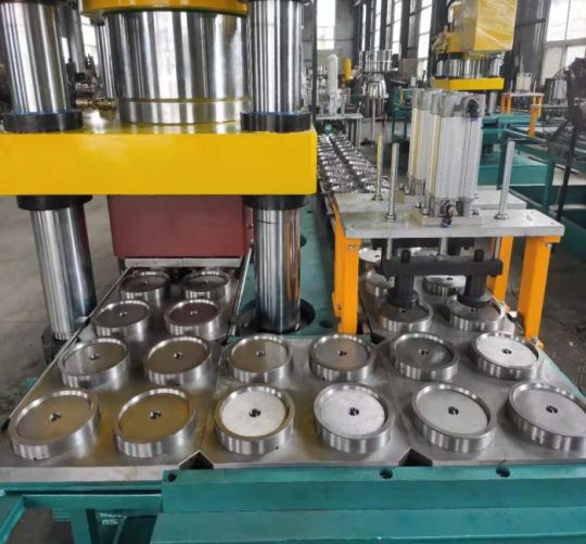
In the world of manufacturing and metalworking, precision is paramount. Whether you're crafting a fine piece of jewelry or constructing a massive bridge, achieving the exact measurements and finishes is crucial. Among the many tools that help us achieve this precision, one often overlooked yet indispensable component is the grinding wheel. In this blog, we will delve into the fascinating world of grinding wheels, exploring their types, applications, and the crucial role they play in shaping our modern world.
Understanding Grinding Wheels
Grinding wheels, also known as abrasive wheels, are essential tools used for various cutting and grinding applications. They consist of abrasive grains bonded together with various materials like resin, ceramic, or metal. These abrasive grains, such as aluminum oxide, silicon carbide, and diamond, are responsible for the grinding action.
Types of Grinding Wheels
Straight Wheels: These are the most common type of grinding wheels, featuring a flat, disk-like shape with a central hole. Straight wheels are versatile and are used for surface grinding, cylindrical grinding, and tool sharpening.
Cylinder Wheels: As the name suggests, these wheels have a cylindrical shape. They are ideal for grinding cylindrical surfaces and contours.
Tapered Wheels: Tapered wheels have a tapered shape and are used for grinding gear teeth and similar applications where precise profiling is necessary.
Diamond Wheels: Diamond grinding wheels are known for their exceptional hardness and abrasion resistance. They are used for grinding hard materials like ceramics, carbides, and gemstones.
Cut-Off Wheels: Cut-off wheels are thin, reinforced wheels designed for cutting through metal, steel, or other materials quickly and precisely.
Challenges and Safety
While grinding wheels are invaluable tools, they come with potential risks. The high-speed rotation of these wheels generates heat, and if not handled correctly, they can cause burns or injuries. Additionally, the release of abrasive dust during grinding can pose respiratory hazards. Therefore, it's essential to wear appropriate safety gear, including safety glasses, gloves, and dust masks when working with grinding wheels.
0 notes
Text
Understanding the Hydraulic Press Brake Machine: Key Components and Uses
The hydraulic press brake machine is a versatile piece of equipment used in metalworking operations. It is used to bend and shape metal sheets into various forms, making it an essential tool in many industries, including construction, automotive, and manufacturing. In this article, we will discuss the key components of the hydraulic press brake machine and its uses.
Key Components of the Hydraulic Press Brake Machine
The hydraulic press brake machine consists of several key components, including the hydraulic system, frame, and bed. The hydraulic system provides the force required to bend the metal sheet. The frame and bed provide the structure to support the hydraulic system and hold the metal sheet in place.
The hydraulic system is comprised of a hydraulic pump, a hydraulic cylinder, and a control valve. The hydraulic pump generates the hydraulic pressure required to power the hydraulic cylinder. The hydraulic cylinder is responsible for applying force to the metal sheet, and the control valve regulates the pressure and flow of the hydraulic fluid.
The frame and bed of the hydraulic press brake machine provide the necessary stability and support for the hydraulic system. The frame is usually made of cast iron or steel and is designed to withstand the forces applied by the hydraulic cylinder. The bed is the flat surface where the metal sheet is placed for bending.
Uses of the Hydraulic Press Brake Machine
The hydraulic press brake machine is primarily used for bending and shaping metal sheets. It is used in a wide range of applications, including the manufacturing of parts for machinery, automobiles, and aircraft. It is also used in the construction industry to create metal components for buildings and bridges.
The hydraulic press brake machine is a versatile tool that can be used for various types of metal bending, including V-bending, U-bending, and air bending. It can bend metal sheets of different thicknesses and lengths, making it suitable for both small and large-scale metalworking operations.
One of the main advantages of the hydraulic press brake machine is its precision. It can produce accurate and consistent bends, making it ideal for creating complex shapes and parts. The hydraulic system provides a high level of control, allowing operators to adjust the pressure and speed of the hydraulic cylinder for optimal results.
A hydraulic press brake machine is a crucial piece of equipment in the metalworking industry. Its key components include the hydraulic system, frame, and bed. It is used for bending and shaping metal sheets and is ideal for creating complex shapes and parts with a high degree of precision. With its versatility and accuracy, the hydraulic press brake machine is a valuable investment for any metalworking operation. Whether you are looking to bend metal sheets into specific shapes or form curves and contours, a hydraulic press brake machine is a versatile and reliable tool that is sure to meet your needs.
0 notes
Text
THE ULTIMATE GUIDE TO PRESSES, SHEARS, LASER CUTTERS AND PUNCHES
In the world of metal fabrication, several key machines play a vital role in shaping and cutting metal with precision and efficiency. This ultimate guide provides comprehensive knowledge and insights into the essential products of the industry: Press Brake, Press Brake Tools, Shearing Machine, Laser Cutting Machine, and Power Press. Whether you are a beginner or an experienced professional, this guide will equip you with the necessary information to understand, select, and optimize the use of these machines for your metalworking needs.
Press Brake:
1.What is a Press Brake?
A press brake is a key equipment used in the field of metal fabrication for bending and folding metal sheets. It utilizes pressure to bend the metal sheet into the desired shape. It is commonly used to create bent parts, enclosures, tubing, and other metal components.
https://ljglobalcloud.oss-cn-hongkong.aliyuncs.com/wp-content/uploads/hating/2023/07/press-brake.jpg
Press brakes typically have the following features and capabilities:
(1)Bending capacity: Press brakes can achieve bends at different angles and radii to meet various workpiece requirements.
(2)Precision: High precision bending results can be achieved by adjusting the position of the upper and lower dies.
(3)Automation: Some modern press brakes are equipped with CNC systems, allowing for automated operation and programming.
(4)Versatility: Press brakes can be used for various bending tasks and different types of metal materials by changing different tools and dies.
(5)Safety: Press brakes are typically equipped with safety devices such as light curtains, protective covers, and emergency stop buttons to ensure operator safety.
Press brakes are widely used in industries such as automotive manufacturing, aerospace, construction, electronics, and more. They are essential equipment for achieving precise and efficient metal fabrication.
2.Types of Press Brakes
There are several types of press brakes commonly used in metal fabrication:
Mechanical Press Brake: Uses a mechanical flywheel and clutch system for bending.
Hydraulic Press Brake: Utilizes hydraulic cylinders for precise bending control.
Servo-Electric Press Brake: Uses electric servo motors for high precision bending.
Pneumatic Press Brake: Relies on compressed air for lighter applications.
CNC Press Brake: Equipped with computerized controls for automated and precise bending operations.
The choice of press brake depends on factors such as material type, thickness, bending requirements, and production volume.
3.Components and Working Principles
A press brake consists of several key components that work together to perform the bending operation. Here are the main components and their functions:
Frame: The frame provides structural support and stability to the press brake.
Bed: The bed is a flat surface where the material to be bent is placed.
Ram: The ram is the moving part of the press brake that applies force to the material for bending.
Die: The die is a tool that shapes the material by providing a specific bending angle.
Punch: The punch is another tool that presses against the material, working in conjunction with the die to bend it.
Backgauge : The backgauge is an adjustable device that positions the material accurately for consistent bending.
4.Key Features and Benefits
Material Placement: The operator places the metal sheet or plate on the bed of the press brake.
Tool Setup: The appropriate die and punch are selected and installed on the press brake.
Backgauge Adjustment: The backgauge is adjusted to position the material correctly for the desired bend.
Bending Process: The ram moves downward, applying force to the material, which is sandwiched between the punch and the die. This bending action creates the desired angle in the material.
Material Removal: Once the bending is complete, the operator removes the bent material from the press brake.
5.Applications and Industries
Press brakes are widely used in various industries for different applications, including:
Metal Fabrication: Press brakes are commonly used in metal fabrication shops to bend and shape metal sheets and plates for various products such as enclosures, brackets, frames, and panels.
Automotive Industry: Press brakes are used in the automotive industry for manufacturing components like chassis, brackets, and body panels.
Aerospace Industry: Press brakes are utilized in the aerospace industry for bending and forming metal parts used in aircraft structures and components.
Construction and Architecture: Press brakes are used in the construction and architectural sectors for bending metal components used in building structures, facades, and decorative elements.
Electronics and Appliances: Press brakes are employed in the manufacturing of electronic enclosures, appliance components, and consumer products.
Press Brake Tools:
1.Importance of Press Brake Tools
Press brake tools play a crucial role in the performance and efficiency of press brake machines. Here are some key points highlighting the importance of press brake tools:
(1) Precision Bending: Press brake tools are designed to provide precise and accurate bending angles. They ensure consistent results and help meet the required specifications for the final product. The quality and precision of the tools directly impact the overall quality of the bent parts.
(2) Versatility: Press brake tools come in various shapes, sizes, and configurations to accommodate different bending requirements. They can be customized or interchanged to achieve different bending angles, radii, or complex shapes. This versatility allows manufacturers to produce a wide range of products using the same machine.
(3) Durability and Longevity: Press brake tools are made from high-quality materials such as hardened steel or special alloys, which make them highly durable and resistant to wear and tear. Proper maintenance and regular tool inspections ensure their longevity, reducing the need for frequent replacements.
(4) Efficiency and Productivity: Well-designed press brake tools optimize the bending process, reducing setup time, and increasing productivity. They enable faster bending cycles, allowing manufacturers to produce more parts in less time. Efficient tooling also minimizes material waste and improves overall production efficiency.
(5) Cost Savings: Using the right press brake tools can lead to cost savings in multiple ways. Accurate bending reduces material waste, saving on raw material costs. Efficient tooling reduces setup time and increases machine productivity, maximizing the output per hour. Additionally, durable tools have a longer lifespan, reducing the frequency of replacements and maintenance costs.
(6) Safety: Press brake tools are designed with safety features in mind. They provide proper clamping and holding mechanisms to secure the material during bending, minimizing the risk of accidents. Additionally, using high-quality tools reduces the chances of tool failure or breakage, ensuring operator safety.
2.Types of Press Brake Tools (including ARC Press Brake Tools)
There are several types of press brake tools available, each designed for specific bending applications. Here are some common types of press brake tools:
V-Die: V-dies are the most commonly used press brake tools. They consist of a bottom die with a V-shaped groove and a punch with a matching V-shaped tip. V-dies are versatile and can be used for a wide range of bending angles and materials.
(1) Bottoming Die: Bottoming dies, also known as flat dies, have a flat surface instead of a V-shaped groove. They are used for achieving sharp bends or bending thicker materials where a tighter radius is required.
(2) Gooseneck Punch: Gooseneck punches have a curved shape that allows for deep and offset bends. They are commonly used for bending channels, boxes, and other complex shapes.
(3) Hemming Tool: Hemming tools are used for creating hems or flanges on the edge of a sheet metal part. They consist of a punch and die set that folds the material over itself to create a secure edge.
(4) Radius Tool: Radius tools, also known as radius punches or radius dies, are used for creating curved bends with a specific radius. They are available in various sizes to accommodate different bending requirements.
(5) Multi-V Die: Multi-V dies have multiple V-shaped grooves of different sizes on a single die. They allow for quick and easy tool changes without the need for separate dies for different bending angles.
(6) ARC Press Brake Tools: ARC press brake tools are specialized tools used for bending sheet metal into arc shapes. They are designed to create precise and consistent curved bends, commonly used in applications such as cylindrical parts, tubes, or curved profiles.
ARC press brake tools typically consist of a bottom die with a curved groove and a punch with a matching curved tip. They enable the accurate and repeatable bending of sheet metal into various arc shapes.
3.Material Selection and Coatings
When it comes to press brake tools, material selection and coatings play an important role in their performance and longevity. Here's a brief overview of material selection and coatings for press brake tools:
Material Selection:
(1) Tool Steel: Tool steel, such as D2 or A2, is commonly used for press brake tools due to its high hardness, wear resistance, and toughness.
(2) Carbide: Carbide inserts or tips are used for heavy-duty applications or when bending abrasive materials. Carbide provides excellent wear resistance but is more brittle than tool steel.
(3) High-Speed Steel (HSS): HSS is another option for press brake tools. It offers good toughness and wear resistance, but not as high as tool steel.
Coatings:
(4) Nitride Coating: Nitride coatings, such as TiN (Titanium Nitride) or TiCN (Titanium Carbonitride), improve the surface hardness and wear resistance of the tool. They are suitable for general-purpose bending applications.
(5) DLC Coating: DLC (Diamond-Like Carbon) coatings provide excellent hardness, low friction, and high wear resistance. They are ideal for bending stainless steel and other difficult-to-form materials.
(6) PVD Coating: Physical Vapor Deposition (PVD) coatings, like TiAlN (Titanium Aluminum Nitride), enhance the tool's performance by reducing friction and increasing wear resistance.
(7) Chrome Plating: Chrome plating is a common coating for press brake tools. It provides good corrosion resistance and reduces friction during bending operations.
The selection of material and coating depends on factors such as the type of material being bent, the bending application, and the desired tool life. It's important to choose the right combination of material and coating to ensure optimal performance and durability of the press brake tools.
4.Tooling Configurations and Considerations
When it comes to press brake tools, the tooling configurations and considerations are crucial for achieving accurate and efficient bending operations. Here are some important aspects to consider:
Tooling Configurations:
(1) V-Die: The V-die is the female tool that provides the desired bend shape. It comes in various widths and angles to accommodate different material thicknesses and bending requirements.
(2) Punch: The punch is the male tool that contacts the material and applies force to create the bend. It also comes in different shapes and sizes to achieve specific bend angles and radii.
(3) Multi-V Die: Multi-V dies have multiple V-shaped grooves of different widths and angles. They allow for bending different material thicknesses and angles without changing the die.
(4) Gooseneck Punch: Gooseneck punches have a curved shape that allows for deep or offset bends where space is limited.
(5) Hemming Tools: Hemming tools are used for creating hemmed edges or flanges on sheet metal.
Considerations:
(1) Material Thickness: The tooling configuration should be selected based on the material thickness being bent. Thicker materials may require larger tooling to accommodate the increased force and prevent tool damage.
(2) Material Type: Different materials have varying properties, such as hardness and ductility, which can affect the tooling selection. Harder materials may require tougher tooling materials or coatings.
(3) Bend Angle and Radius: The desired bend angle and radius dictate the selection of punch and die configurations. Sharp bends require smaller punch radii, while larger radii are needed for gentler bends.
(4) Tooling Alignment: Proper alignment between the punch and die is essential for achieving accurate and consistent bends. Misalignment can result in uneven bends or tool damage.
(5) Tooling Maintenance: Regular inspection and maintenance of the tooling are necessary to ensure optimal performance and longevity. This includes cleaning, lubrication, and replacement of worn-out components.
By considering the tooling configurations and these important factors, you can select the appropriate press brake tools for your specific bending requirements. This will help you achieve precise and efficient bending operations while prolonging the tooling life.
5.Tool Maintenance and Longevity
(1) Regular cleaning: Clean the press brake tools regularly to remove debris, dirt, and metal shavings. Use appropriate cleaning agents and tools to avoid damaging the tool surfaces. Ensure that the tools are completely dry before storing them.
(2) Lubrication: Apply lubrication to the press brake tools as recommended by the manufacturer. Lubrication helps reduce friction and wear, improving the tool's lifespan. Follow the manufacturer's guidelines for the type and frequency of lubrication.
(3) Inspection and repair: Regularly inspect the press brake tools for signs of wear, damage, or deformation. Check for any cracks, chips, or excessive wear on the cutting edges. If any issues are detected, promptly repair or replace the damaged parts to prevent further damage and ensure accurate bending results.
(4) Proper storage: Store the press brake tools in a clean and dry environment to prevent corrosion and damage. Use dedicated tool racks or boxes to keep the tools organized and protected. Avoid placing heavy objects on top of the tools to prevent deformation.
(5) Operator training: Proper training of operators is essential for tool maintenance and longevity. Educate operators on the correct usage techniques, operating limits, and safety precautions. Encourage operators to report any issues or abnormalities with the tools promptly.
By following these maintenance tips, you can extend the lifespan of your press brake tools and ensure consistent and accurate bending operations. Regular maintenance not only improves tool performance but also contributes to the overall safety and efficiency of the bending process.
6.Advanced Tooling Technologies and Innovations
Advanced tooling technologies and innovations have significantly improved the performance and capabilities of press brake tools. Here are some key advancements in press brake tooling:
(1) High-strength materials: Press brake tooling is now made from high-strength materials such as hardened steel alloys or carbide. These materials offer superior durability, wear resistance, and longer tool life compared to traditional tooling materials.
(2) Coatings and surface treatments: Advanced coatings and surface treatments, such as TiN (Titanium Nitride) or DLC (Diamond-Like Carbon), are applied to press brake tools to enhance their performance. These coatings reduce friction, improve wear resistance, and prevent material adhesion, resulting in improved bending quality and longer tool life.
(3) Precision tooling systems: Modern press brake tooling systems feature precision-ground tooling with tight tolerances. These systems ensure accurate and repeatable bending results, reducing setup times and increasing productivity.
(4) Quick-change tooling systems: Quick-change tooling systems allow for rapid tooling setup and changeovers. These systems utilize standardized tooling holders and clamping mechanisms, enabling operators to switch between different tooling setups quickly and efficiently.
(5) 3D modeling and simulation: Advanced software tools enable 3D modeling and simulation of bending processes. These tools help optimize tooling designs, simulate bending sequences, and detect potential collision or interference issues before actual production. This reduces setup time, minimizes errors, and improves overall efficiency.
(6) Custom tooling solutions: Tooling manufacturers now offer custom tooling solutions tailored to specific bending applications. These solutions include specialized tool profiles, custom tool coatings, and even tooling with integrated sensors for process monitoring and control.
These advancements in press brake tooling technologies have significantly improved productivity, accuracy, and tool life. By adopting these innovations, manufacturers can achieve higher efficiency, reduce downtime, and produce high-quality bent parts consistently.
Shearing Machine:
1.Understanding Shearing Machines
Shearing machines are industrial mechanical devices used for cutting metal sheets and other materials. They apply shearing force to cut the materials into desired shapes and sizes. Shearing machines are widely used in manufacturing and metalworking industries to produce various products and components.
The working principle of shearing machines involves placing the material on a shear table and applying force through cutting blades to cause the material to fracture. Shearing machines can perform operations such as straight cutting, curved cutting, and angle cutting. Depending on the specific requirements, shearing machines can have different cutting capacities and precision.
There are various types of shearing machines, including hydraulic shearing machines, mechanical shearing machines, and manual shearing machines. Hydraulic shearing machines use hydraulic systems to provide cutting force and offer high power and precision, making them suitable for large-scale and heavy-duty cutting tasks. Mechanical shearing machines use mechanical mechanisms to provide cutting force and are typically more compact and cost-effective, suitable for medium-sized cutting tasks. Manual shearing machines require manual operation and are suitable for small-scale and simple cutting work.
The cutting capacity of shearing machines depends on their maximum cutting thickness and cutting width. Larger shearing machines generally have higher cutting capacity and can handle thicker and wider materials. The cutting precision of shearing machines is influenced by factors such as blade sharpness, adjustment of blade clearance, rigidity of the frame, and material characteristics.
Safety considerations are important when operating shearing machines. Operators should receive proper training on the operation procedures and safety precautions of shearing machines. Additionally, appropriate personal protective equipment, such as safety goggles and gloves, should be worn. Regular inspection and maintenance of shearing machines are necessary to ensure their proper functioning and safe operation. Following the operation manual and manufacturer's recommendations is crucial to ensure the safety and effectiveness of operating shearing machines.

2.Hydraulic vs. Mechanical Shearing Machines
Hydraulic and mechanical shearing machines are two common types of shearing machines used in industrial applications. Here's a comparison between the two:
Power Source:
(1) Hydraulic Shearing Machines: These machines use a hydraulic system to generate the cutting force. The force is applied through hydraulic cylinders powered by a hydraulic pump. Hydraulic shearing machines offer high power and can handle heavy-duty cutting operations.
(2) Mechanical Shearing Machines: These machines use mechanical mechanisms, such as gears, levers, and flywheels, to generate the cutting force. The force is applied directly through the mechanical components. Mechanical shearing machines are generally more compact and cost-effective.
Power and Precision:
(1) Hydraulic Shearing Machines: Due to the hydraulic system, hydraulic shearing machines can provide high cutting power. They are capable of cutting thick and hard materials with precision. The hydraulic system allows for better control and adjustment of the cutting force, resulting in accurate and consistent cuts.
(2) Mechanical Shearing Machines: Mechanical shearing machines provide a lower cutting power compared to hydraulic ones. They are suitable for medium-duty cutting tasks. However, the cutting precision of mechanical shearing machines can be affected by factors such as mechanical wear and tear, which may require more frequent adjustments and maintenance.
Size and Space:
(3) Hydraulic Shearing Machines: Hydraulic shearing machines are generally larger and require more space due to the hydraulic system components, such as the hydraulic pump, cylinders, and hoses.
(4) Mechanical Shearing Machines: Mechanical shearing machines are more compact and take up less space. They are often preferred in smaller workshops or where space is limited.
Cost:
(1) Hydraulic Shearing Machines: Hydraulic shearing machines are typically more expensive due to the complexity and cost of the hydraulic system components.
(2) Mechanical Shearing Machines: Mechanical shearing machines are generally more affordable and cost-effective.
In summary, hydraulic shearing machines provide high power and precision, making them suitable for heavy-duty cutting operations. They are larger and more expensive. On the other hand, mechanical shearing machines are more compact, cost-effective, and suitable for medium-duty cutting tasks. The choice between hydraulic and mechanical shearing machines depends on the specific cutting requirements, available space, and budget considerations.
3.Components and Operation
Components of a Shearing Machine:
(1) Shear Table: This is the flat surface or bed on which the material to be cut is placed. It provides support and stability during the cutting process.
(2) Cutting Blades: These are the sharp blades that perform the actual cutting of the material. They are typically made of high-quality tool steel and are securely mounted on the machine. The blades can be straight, curved, or angled, depending on the desired cutting operation.
(3) Blade Clearance Adjustment: Shearing machines often have a mechanism for adjusting the clearance between the upper and lower blades. This adjustment allows for precise control of the cutting gap, ensuring clean and accurate cuts.
(4) Back Gauge: The back gauge is a movable stop or fence located behind the shear table. It helps in positioning the material accurately for repetitive cutting operations. The back gauge can be manually adjusted or controlled by a motorized system.
(5) Drive System: The drive system provides the power to move the cutting blades. In hydraulic shearing machines, the drive system consists of a hydraulic pump, cylinders, and valves. In mechanical shearing machines, it typically involves mechanical components such as gears, levers, and flywheels.
(6) Control Panel: The control panel houses the controls and switches for operating the shearing machine. It allows the operator to start and stop the machine, adjust settings, and monitor the cutting process.
Operation of a Shearing Machine:
(1) Material Preparation: The material to be cut is prepared by ensuring it is clean, straight, and properly aligned with the shear table. Any protective coatings or films on the material should be removed.
(2) Material Placement: The material is placed on the shear table, ensuring it is aligned with the back gauge if applicable. The operator should take care to position the material securely and avoid any obstructions that could interfere with the cutting process.
(3) Blade Clearance Adjustment: The blade clearance is set according to the thickness and type of material being cut. This adjustment ensures proper shearing without damaging the material or the blades. The manufacturer's guidelines or machine manual should be followed for the correct blade clearance settings.
(4) Cutting Operation: Once the material is properly positioned and the blade clearance is set, the operator initiates the cutting operation. In hydraulic shearing machines, the hydraulic pump is activated to provide the necessary cutting force. In mechanical shearing machines, the operator engages the drive system, which transfers power to the cutting blades.
(5) Monitoring and Control: During the cutting process, the operator monitors the operation to ensure smooth and accurate cutting. The control panel may provide indicators or displays for monitoring the cutting speed, blade position, and other parameters. Any abnormalities or issues should be addressed promptly.
(6) Material Removal and Repeat: After the cutting operation is complete, the cut pieces are removed from the shear table. The process can be repeated for subsequent cuts, adjusting the back gauge if necessary.
It's important to note that the specific operation of a shearing machine may vary depending on the machine model and manufacturer. Operators should always refer to the machine's manual and receive proper training before operating the shearing machine.
4.Cutting Capacity and Accuracy
Cutting Capacity and Accuracy are important considerations when using a shearing machine. Let's discuss each of them:
Cutting Capacity:
(1) Shearing machines have a specified cutting capacity, which refers to the maximum thickness and width of the material that can be effectively cut. The cutting capacity is determined by factors such as the power of the machine, the strength of the blades, and the rigidity of the shear table.
(2) It is crucial to choose a shearing machine with a cutting capacity that matches the requirements of the materials you will be working with. Attempting to cut materials beyond the machine's capacity can result in poor cutting quality, blade damage, or even machine malfunction.
Cutting Accuracy:
(1) Cutting accuracy refers to the ability of the shearing machine to make precise and consistent cuts. It is influenced by several factors, including the design and condition of the machine, the sharpness and alignment of the blades, and the control and monitoring systems.
(2) To achieve high cutting accuracy, it is important to maintain the shearing machine properly. Regular blade sharpening and replacement, as well as routine maintenance and calibration, can help ensure accurate cuts.
(3) The operator's skill and experience also play a significant role in achieving cutting accuracy. Proper material positioning, adjustment of blade clearance, and careful monitoring of the cutting process are essential for obtaining precise and clean cuts.
Factors Affecting Accuracy:
(1) Blade Condition: Dull or damaged blades can lead to uneven cuts and reduced accuracy. Regular inspection and maintenance of the blades are necessary to maintain cutting precision.
(2) Blade Clearance: Incorrect blade clearance can result in distorted or incomplete cuts. It is important to set the appropriate blade clearance for the material being cut.
(3) Material Alignment: Proper alignment of the material with the shear table and back gauge is crucial for accurate cuts. Misalignment can cause crooked or uneven cuts.
(4) Machine Rigidity: The rigidity of the shearing machine, including the shear table and frame, affects cutting accuracy. A sturdy and well-maintained machine provides better stability and reduces the chances of deflection during the cutting process.
It is recommended to follow the manufacturer's guidelines and recommendations for the specific shearing machine being used. Regular maintenance, blade inspection, and operator training are essential to ensure optimal cutting capacity and accuracy.
5.Safety Considerations
Safety considerations are of utmost importance when operating a shearing machine. Here are some key safety measures to keep in mind:
(1) Read and Follow the Manual: Familiarize yourself with the manufacturer's instructions and safety guidelines provided in the machine's manual. Understand the machine's features, controls, and potential hazards before operating it.
(2) Personal Protective Equipment (PPE): Always wear appropriate PPE, including safety glasses or goggles, gloves, and ear protection. Depending on the specific machine and the materials being cut, additional protective gear such as a face shield or apron may be required.
(3) Machine Inspection: Before starting the machine, inspect it for any signs of damage, loose parts, or malfunctioning components. Ensure that all safety guards and devices are in place and functioning correctly.
(4) Training and Competence: Only trained and authorized personnel should operate a shearing machine. Proper training should cover machine operation, safety procedures, emergency shutdown, and handling of materials.
(5) Material Handling: Use caution when handling materials, especially large or heavy ones. Use lifting equipment or assistance when necessary to avoid strain or injuries.
(6) Emergency Stop: Familiarize yourself with the location and operation of the emergency stop button or switch. Be prepared to use it in case of any emergency or unsafe situation.
(7) Blade Safety: Never reach into the cutting area while the machine is in operation or attempt to adjust the blades without proper training. Always wait for the machine to come to a complete stop before making any adjustments or maintenance.
(8) Housekeeping: Maintain a clean and organized work area. Remove any debris, scraps, or obstructions that may interfere with the machine's operation or cause accidents.
(9) Lockout/Tagout: Follow proper lockout/tagout procedures when performing maintenance or repairs on the machine. This involves disconnecting the power source and ensuring that it cannot be re-energized accidentally.
(10) Regular Maintenance: Adhere to the recommended maintenance schedule for the shearing machine. This includes blade sharpening, lubrication, and inspection of mechanical and electrical components.
Remember, safety should always be the top priority when operating any machinery. If you have any concerns or encounter any issues with the shearing machine, stop the operation immediately and seek assistance from a qualified technician or supervisor.
Laser Cutting Machine:
1.Introduction to Laser Cutting:
Laser cutting is a highly precise and versatile method of cutting various materials using a high-powered laser beam. It has revolutionized the manufacturing industry by providing a faster, more accurate, and more efficient alternative to traditional cutting methods. Laser cutting machines are used in a wide range of industries, including automotive, aerospace, electronics, signage, and jewelry making.
https://ljglobalcloud.oss-cn-hongkong.aliyuncs.com/wp-content/uploads/hating/2023/07/Laser-Cutting-Machine-1.png
2.Types of Laser Cutting Machines:
There are different types of laser cutting machines available, each with its own advantages and suitable applications. The most common types include CO2 lasers, fiber lasers, and neodymium lasers.
CO2 lasers are the most widely used type of laser cutting machine. They use a mixture of carbon dioxide, nitrogen, and helium as the laser medium. CO2 lasers are versatile and can cut a wide range of materials, including non-metallic materials such as plastics, wood, and fabrics, as well as metals.
Fiber lasers use optical fibers as the laser medium. They are highly efficient and are primarily used for cutting metals, including stainless steel, aluminum, and copper. Fiber lasers offer high beam quality, which results in faster cutting speeds and improved precision.
Neodymium lasers use neodymium-doped crystals (such as neodymium-doped yttrium aluminum garnet or Nd: YAG) as the laser medium. They are known for their high energy and are used for precision cutting and engraving. Neodymium lasers are commonly used in applications that require high power and fine detail, such as jewelry making and micro-machining.
3.Advantages and Limitations:
Laser cutting offers several advantages over traditional cutting methods. One of the key advantages is its high precision and accuracy. Laser cutting machines can achieve intricate and complex cuts with minimal distortion. They also provide excellent edge quality, eliminating the need for additional finishing processes.
Another advantage is the speed and efficiency of laser cutting. Laser cutting machines can cut at high speeds, resulting in faster production times and increased productivity. They can also cut multiple parts simultaneously, further improving efficiency.
Laser cutting is a non-contact cutting method, which means there is no physical contact between the cutting tool and the material. This reduces the risk of damage to the material and allows for cutting delicate or fragile materials.
However, laser cutting does have some limitations. The thickness capacity of a laser cutting machine depends on the power of the laser and the type of material being cut. Thicker materials may require multiple passes or a more powerful laser to achieve a clean cut. Additionally, laser cutting machines can be expensive to purchase and maintain, making them more suitable for high-volume production environments.
4.Material Compatibility and Thickness:
Laser cutting machines can cut a wide range of materials, including metals, plastics, wood, textiles, and more. The compatibility of a material with laser cutting depends on its ability to absorb the laser energy. Materials that are highly reflective, such as copper or aluminum, may require higher laser power for cutting.
The thickness of the material that can be cut depends on the power of the laser and the type of material. Laser cutting machines can typically cut thin materials with high precision. For example, a CO2 laser cutting machine can cut up to 25mm thick steel, while a fiber laser cutting machine can cut up to 30mm thick steel. However, the maximum thickness capacity may vary depending on the specific machine and laser power.
It is important to consider the material compatibility and thickness capacity of a laser cutting machine before selecting the appropriate machine for a specific application. Consulting with a laser cutting machine supplier or manufacturer can help determine the best machine for a particular material and thickness requirement.
Power Press:
1.Exploring Power Press Machines:
Power press machines, also known as press machines or stamping presses, are versatile machines used in metalworking for various operations such as punching, bending, forming, and blanking. They are commonly used in industries such as automotive, manufacturing, construction, and appliance production. Power press machines come in different sizes and configurations to accommodate different applications and production requirements.
Power press machines are designed to apply force to a workpiece using mechanical or hydraulic systems. They are capable of exerting high pressure to shape, cut, or form metal sheets or other materials. Power press machines can be categorized into mechanical and hydraulic types based on their power source and operation.
2.Mechanical vs. Hydraulic Power Press:
Mechanical power presses use mechanical force, typically generated by a flywheel and a crankshaft, to perform operations. They are known for their high speed and productivity. Mechanical power press machines have a mechanical clutch or brake system that controls the stroke and stopping motion of the ram. They are suitable for high-volume production environments where speed and precision are important.
Hydraulic power presses, on the other hand, use hydraulic systems to generate force. They utilize hydraulic cylinders to apply pressure to the ram and perform operations. Hydraulic power press machines offer more control and flexibility in terms of force adjustment and speed modulation. They are often used for operations that require precise force control or for applications that involve deep drawing or forming of materials.
The choice between a mechanical or hydraulic power press depends on the specific requirements of the application. Factors such as the type of operation, material thickness, production volume, and precision requirements should be considered when selecting the appropriate power press machine.
3.Components and Operation:
Power press machines consist of several key components that work together to perform various operations. These components include the frame, slide or ram, bolster, die, clutch or brake system, and control system.
The frame provides the structure and support for the machine. It is usually made of cast iron or steel to withstand the forces exerted during operation. The slide, also known as the ram, moves up and down to apply force to the material. It is guided by the frame and can be driven by a crankshaft or hydraulic cylinders.
The bolster is a flat surface on which the material is placed. It provides support to the workpiece during the operation. The die is a specially shaped tool that performs the desired operation, such as punching a hole or bending a metal sheet. The die is mounted on the bolster or the ram, depending on the type of operation.
The clutch or brake system controls the stroke and stopping motion of the ram. In mechanical power press machines, a mechanical clutch or brake is used to engage or disengage the flywheel, controlling the motion of the ram. In hydraulic power press machines, the hydraulic system controls the movement of the ram.
The control system of a power press machine can vary depending on the specific machine and its features. It can range from simple manual controls to advanced computer numerical control (CNC) systems. CNC systems offer precise control over the machine's operation, allowing for programmable and repeatable processes.
4.Punching, Bending, and Forming Capabilities:
Power press machines are capable of performing various operations, depending on the tooling and dies used. Some common operations include punching, bending, forming, blanking, coining, embossing, and deep drawing.
Punching is a process of creating holes or shapes in a material using a punch and die set. Bending is the process of deforming a material to form angles or curves. Forming involves shaping a material to create three-dimensional objects or complex geometries. Blanking is the process of cutting out a flat shape from a larger piece of material. Coining is a process that involves compressing a material to create a precise shape or pattern. Embossing is the process of creating raised or depressed
Conclusion:
By delving into the comprehensive knowledge provided in this ultimate guide, you have gained a solid understanding of Press Brake, Press Brake Tools, Shearing Machine, Laser Cutting Machine, and Power Press. Armed with this knowledge, you can confidently select, operate, and optimize these machines to achieve precise and efficient metal fabrication results. Remember to prioritize safety, regular maintenance, and stay updated with the latest advancements in the industry to stay ahead in the ever-evolving world of metalworking.
0 notes
Text
Laser Tube Cutting Equipment: A Comprehensive Guide
Introduction
This machine has revolutionized metalworking, enabling manufacturers to achieve intricate cuts and designs with exceptional precision. Due to the technology's capacity to dramatically reduce manufacturing time and boost productivity, it has become extremely popular across a variety of industries. In this article, we will explore the world of laser tube cutting equipment, with a specific focus on the advanced Fiber Laser Tube Cutting Machine.

Understanding Laser Tube Cutting Equipment
It utilizes high-powered lasers to cut through metal tubes with remarkable accuracy. The procedure entails aiming the laser beam at the tube's surface, which heats and melts the material, creating a clean and precise cut. This method offers distinct advantages over traditional cutting techniques, such as sawing and shearing, as it eliminates the need for complex tooling and reduces material wastage.
Fiber Laser Tube Cutting Machine: A Game-Changer
Modern technology has completely changed the metalworking sector with the Fiber Laser Tube Cutting Machine. Unlike its CO2 laser counterparts, the fiber laser source in this machine offers exceptional energy efficiency, lower maintenance requirements, and higher cutting speeds. These advantages make this machine an ideal choice for manufacturers looking to enhance their productivity while reducing operating costs.
Key Features of Fiber Laser Tube Cutting Machine
Versatility
Fiber Laser Tube Cutting Machines are highly versatile and can cut through a vast range of materials, including steel, stainless steel, brass, aluminum, copper, and more. This versatility allows manufacturers to process different materials without the need for multiple machines.
Precision
The precision offered by the Machine is unrivaled. Its high-quality laser beam allows for intricate cuts, sharp edges, and complex designs, making it a perfect choice for industries that demand the utmost precision in their products.
Automation
Numerous Fiber Laser Cylinder Cutting Machines come furnished with cutting-edge mechanization highlights, such as robotic loaders and unloaders. These features streamline the cutting process, reduce manual intervention, and enhance overall efficiency.
lxcuttingmachine.com: Your Source for Cutting Solutions
As the demand for laser tube cutting equipment grows, lxcuttingmachine.com emerges as a reliable provider of high-quality machines and metal tube processing solutions. Our company providing manufacturers with numerous options to cater to their specific needs. Additionally, we take pride in offering non-standard customization services, ensuring that each machine is tailored to meet the unique requirements of our customers.
Advantages of Partnering with lxcuttingmachine.com
Wide Range of Options
Our company boasts dozens of series of laser pipe-cutting machines, allowing customers to select the model that best fits their production demands and budget.
Expert Guidance
Our knowledgeable staff is committed to aiding customers in selecting the best laser tube-cutting machinery for their needs. We provide valuable insights and technical support to ensure the seamless integration of our machines into their production processes.
High-Quality Service
At lxcuttingmachine.com, we prioritize customer satisfaction. Our commitment to delivering top-notch service, on-time delivery, and post-sale support sets us apart from the competition.
Non-Standard Customization
Understanding that each customer's needs are unique, we offer non-standard customization services, allowing for the inclusion of specific features and functionalities in our Fiber Laser Tube Cutting Machines.
Conclusion
In conclusion, laser tube cutting equipment, particularly the Fiber Laser Tube Cutting Machine, has become a game-changer in the metalworking industry. With its unmatched precision, cutting speed, and versatility, it has transformed the way metal tubes are processed, benefiting numerous industries worldwide.
Kindly inform us if you require some other information.
Fiber Laser Pipe Cutter
High Speed Tube Cutting Machine
Fiber Laser Tube Cutting
0 notes
Last Seen Blogs

littlesauasks
Ask Adventure Time + Fionna and Cake Littles Au

cockstrology
Astrology hoe

kingdoms-edge
kingdom's edge

7-mers
7-mers.tumlr.com

youngblood-2120
Life As A Fangirl.