#Loopback device
Text
Loopback device

#Loopback device how to#
#Loopback device for mac#
There is no mechanism to change the sampling rate in Garageband, but in doing this project I discovered (and demonstrate) that I could receive and record audio from a 48k Jacktrip session even though Garageband only runs at 44.1k. Variation 4: Capturing audio in a DAW (Garageband) – Click here for video Variation 3: Capturing audio in a DAW (Max) – Click here for video But be careful to launch Live and confirm settings before launching the Jacktrip session – Live may be configured wrong when it launches and take down Jacktrip Variation 2: Capturing audio in a DAW (Ableton Live) – Click here for videoĪll the audio settings are set globally in Live. Launching a mismatched project will crash the Jacktrip session, possibly for everybody. The one that causes trouble is the Sample Rate, which is set at the project level and is quite often different than the sample rate being used by Jacktrip. The quirk of Logic is that it sets audio preferences in two places. Variation 1: Capturing audio in a DAW (Logic Pro) – Click here for video A device that can route 2 channels of Jacktrip in and out. Step 6: Route local audio out to Jacktrip – Click here for video Start by launching a Jacktrip connection and routing the incoming Jacktrip audio (just to the interface at first, more apps in later examples). Step 5: Route incoming Jacktrip audio – Click here for video Those other devices can be turned back on once this one is selected and saved as a QJackCtl preset. People who are already using Loopback and have a lot of devices may have to turn all but the new one off momentarily so that QJackCtl can find this one. QJackCtl has two buttons that can be used to select the interface - use the rightmost one, with the carrot that looks like this “>” Start QJackCtl at this point and make sure that it works as an interface. Step 4: Link to QJackCtl – Click here for video I’ve gotten into using really goofy names so that I don’t confuse myself when picking this device out of a list. This is also a good place to rename the device. Step 3: Clear out default routings – Click here for videoĪll of the sources and destinations are in place, but there isn’t any routing. Adding things later will sometimes cause Loopback to “rewire” the whole setup. Loopback makes guesses about the routing, which are fine but those guesses won’t work for what we’re doing. It’s good to make a list of sources and destinations for audio and add them all at once. Step 2: Add components – Click here for video This is just like a 2-channel Soundflower or Blackhole device – apps can send 2 channels to this gizmo, and other apps can listen to those two channels. Step 1: Starting out – Click here for videoĬreate a new Loopback device. Step 0: Assumptions – Click here for video Click on the pictures to embiggify and read them. There are links to short videos that “animate” each of these steps and examples.
#Loopback device how to#
I don’t have a clue how to do this on a Windows machine.
#Loopback device for mac#
It also covers things like routing audio into and out of other audio software like Logic Pro, Ableton Live, Max and Zoom.Īlas, this is for Mac folks only. The goal of this post is to get a person with a 2×2 interface going with a setup that will let them join a Jacktrip session reliably, without having to “rewire” things each time. I like it because it is more visual and does more stuff. Loopback is a for-money successor to Soundflower and similar to BlackHole. Here’s a step-by-step post about routing Jacktrip audio using Rogue Amoeba’s Loopback software.
0 notes
Text
Streamlining Connectivity: Exploring the World of MPO/MTP Fiber Optic Solutions
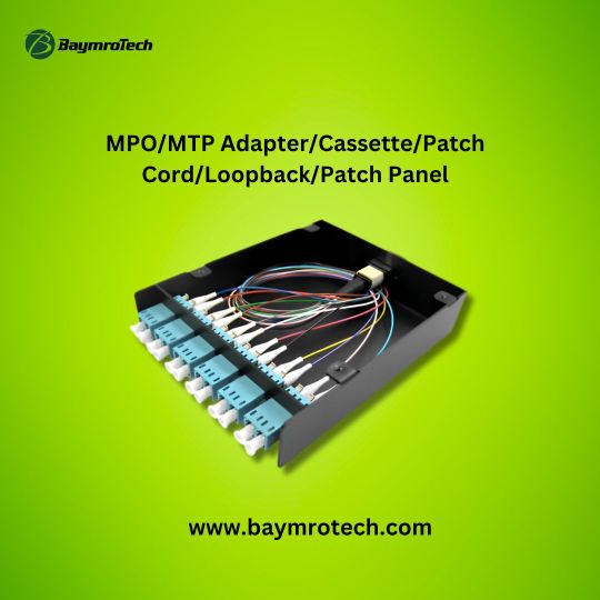
In the realm of fiber optic networking, MPO/MTP solutions have emerged as game-changers, offering efficient, high-density connectivity for a wide range of applications. From adapters and cassettes to patch cords, loopbacks, and patch panels, these innovative components play a crucial role in optimizing network performance and simplifying installation and maintenance processes.
MPO/MTP adapters serve as the backbone of MPO/MTP connectivity, allowing for seamless connections between different types of fiber optic cables and devices. These adapters come in various configurations, including single-mode and multimode, and can accommodate different connector types, such as LC, SC, and MPO/MTP, providing flexibility and compatibility in diverse networking environments.
MPO/MTP cassettes are pre-terminated fiber optic modules that house MPO/MTP connectors and provide a convenient way to manage and organize fiber optic cables within a network. These cassettes come in various configurations, including fiber counts and polarity types, and can be easily installed in patch panels or enclosures, simplifying cable management and minimizing installation time.
Patch cords equipped with MPO/MTP connectors are used to establish direct connections between network devices, such as switches, routers, and servers. These cords come in various lengths and configurations, including single-mode and multimode, and provide reliable and high-performance connectivity for data transmission.
MPO/MTP loopback modules are specialized components used for testing and troubleshooting fiber optic links. These modules feature MPO/MTP connectors on one end and a loopback configuration on the other, allowing signals to be looped back to the transmitter for testing purposes, ensuring network integrity and performance.
Patch panels equipped with MPO/MTP adapters provide a centralized point for terminating and organizing fiber optic cables within a network. These panels come in various configurations, including rack-mount and wall-mount, and offer high-density connectivity for optimizing space utilization in data centers and telecommunications facilities.
In conclusion, MPO/MTP fiber optic solutions offer a comprehensive suite of components for optimizing connectivity, performance, and efficiency in fiber optic networks. From adapters and cassettes to patch cords, loopbacks, and patch panels, these innovative solutions provide the building blocks for seamless and reliable data transmission in today's digital landscape.
0 notes
Text
127.0.0.1 APEX ORACLE

Understanding “127.0.0.1” in Oracle APEX
If you’re venturing into the Oracle Application Express (APEX) world, you’ll likely encounter the address “127.0.0.1”. This seemingly simple string of numbers is unique when setting up and accessing your APEX environment. Let’s break it down:
What is 127.0.0.1?
In computer networking, “127.0.0.1” is an IP address known as the “localhost.” A reserved address always points back to your computer or device. Think of it as your computer talking to itself.
Why is it essential in Oracle APEX?
When installed locally, Oracle APEX typically runs a small web server on your computer. This server allows you to access your APEX workspaces and applications through a web browser.
By default, Oracle APEX is configured to use port 8080.
Therefore, the typical URL to access your APEX installation after setup is http://127.0.0.1:8080/apex.
Let’s break down this URL:
http:// Indicates that the communication will use the Hypertext Transfer Protocol, the foundation of the web.
127.0.0.1 Tells your browser that the web server you want to connect to is on your machine.
:8080 Specifies the port number on which the APEX web server is listening.
/apex Directs your browser to the root of your APEX installation.
Troubleshooting: When Things Don’t Connect
If you cannot access your APEX installation using the 127.0.0.1 address, here are some things to check:
Is the APEX web server running? Checking and starting it depends on your Oracle installation type (like Oracle XE).
Firewall: Is your computer’s firewall blocking access to port 8080? You should configure your firewall settings to allow incoming connections on that port.
Port Conflicts: Is another application already using port 8080? You may need to change the port used by APEX. Information on how to do this can be found in the Oracle APEX documentation.
Beyond the Basics
While “127.0.0.1” is the most common way to access APEX locally, things can get more complex:
Remote Access: You can configure your APEX installation to be accessible from other computers on your network.
Custom Domains: Using network settings, you can map a custom domain name to your APEX installation instead of using the IP address.
Key Takeaways
127.0.0.1 is your computer’s “loopback” address for internal communication.
Oracle APEX typically uses 127.0.0.1 and port 8080 to let you access your workspaces and applications locally.
Understanding these basics will help you troubleshoot connection issues in your APEX environment.
youtube
You can find more information about Oracle Apex in this Oracle Apex Link
Conclusion:
Unogeeks is the No.1 IT Training Institute for Oracle Apex Training. Anyone Disagree? Please drop in a comment
You can check out our other latest blogs on Oracle Apex here – Oarcle Apex Blogs
You can check out our Best In Class Oracle Apex Details here – Oracle Apex Training
Follow & Connect with us:
———————————-
For Training inquiries:
Call/Whatsapp: +91 73960 33555
Mail us at: [email protected]
Our Website ➜ https://unogeeks.com
Follow us:
Instagram: https://www.instagram.com/unogeeks
Facebook: https://www.facebook.com/UnogeeksSoftwareTrainingInstitute
Twitter: https://twitter.com/unogeeks
0 notes
Text
Device Classification and Their Associations in Linux System
Linux Each device on the system has its own set of fixed rules for operation, and there are numerous types and models of devices. It is not practical or meaningful to write the fixed rules for each device into the kernel.
Each device has its corresponding driver to ensure it can operate properly on the system. From a small LED light to a large network card, all devices require relevant drivers A driver can be seen as a layer of software between the application program and the actual device.
An application program controls a device by first sending a signal to the driver. The driver then receives the signal and commands the device to perform the corresponding action. If the application program wants to obtain the data collected by the device, it also needs to be done through the driver.
Classification of device in Linux
Linux systems divide devices into three basic types, and each module is typically implemented as one of these classes.
01 Character device
A character device is a device that can be accessed as a stream of bytes. This feature is implemented by a character device driver. Character device drivers typically implement at least open, close, read, and write system calls.
The character device is a sequential access, and the corresponding information can be read only after the device responds. It cannot be accessed randomly, and each character device has a device number, which consists of a major device number and a minor device number Common character devices such as serial ports and IICs.
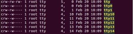
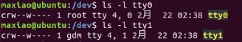
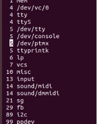
The corresponding files for character devices are in the /dev directory, and each file corresponds to one piece of hardware. In the /dev directory of linux system, use ls -l to view the details, the first letter "c" is the identification of the character device file.
02 Block device
Like character devices, block devices are accessed through the file system node in the/dev directory. File systems can be accommodated on block devices. Common block devices such as disk, emmc flash, NAND flash, SD card, etc. Each block device likewise has r--+'/h vortex【5 slices【a device number, which consists of a primary device number and a secondary device number. Use the command ls -l to view the details in the /dev directory on a linux system. The first letter "b" identifies the block device file. /dev Each block device file under dev corresponds to a partition of the disk.

03 Network equipment
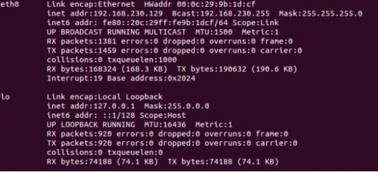
Any network-related transaction goes through a network interface, a device that can exchange data with other hosts. Usually, the interface is a hardware device, but it can also be a purely software device, for example, there is a lo in ifconfig to view information about the network interface, which is the network loopback (loopback) interface.
The way to access the network interfaces is to assign them a unique name, such as eth0, eth1, lo, and so on. However, no corresponding node exists in the file system for this name. Network interfaces do not have a device number like character and block devices, only a unique name such as eth0, eth1, etc., and this name does not need to correspond to a device file node.
The kernel uses a set of functions related to packet transfers to communicate with network device drivers, which differ from the read() and write() methods of character and block devices.
Various character devices and block devices all reflect the linux "everything is a file" design idea; network devices are the only devices that do not reflect this idea.
Device node, device driver and device association
There are many devices mounted on the whole system. When we access a device node, how does the system know which device driver to use and which device to access? This is achieved through the device number.
When creating a device node, you need to specify the major device number and the minor device number. For device nodes, the name is not important, the device number is the most important, which actually specifies the corresponding driver and the corresponding device.
Primary device numbers are used to distinguish between different types of devices, while secondary device numbers are used to distinguish between multiple devices of the same type. For commonly used devices, Linux has agreed-upon numbers, such asHard Disk the master device number of 3.
Use the command ls -l plus name in the /dev directory to view the corresponding primary and secondary device numbers.
Main device
When a driver is initialized, it registers its driver and corresponding master device number with the system so that when an application accesses a device node, the system knows which driver it is accessing. You can drive the master device number of a system device through the /proc/devices file.
Minor equipment number
When the driver runs, it creates a device object for each device it finds that it can drive and assigns it a minor device number to distinguish between different devices. So that when an application accesses a device node, the driver knows which device it is accessing based on the minor number.
Originally published at www.forlinx.net.
0 notes
Text
https://www.china-tscom.com/products/mpo-loopback/
T & S MTP® / MPO fiber loop is a device used for parallel connection tests and an aging test of optical communication equipment. Well-designed by engineers at T&S, our MTP®/MPO loopback adapter can transmit the optical network signal from the transmitter to the receiver, thereby forming the optical signal receiving and transmitting loop. MTP® / MPO fiber loop provides a fast and efficient way to test the transmission capacity and receiving sensitivity of optical network equipment. T & S MTP® / MPO fiber loop has 8F, 12F, 16F, 24F, 32F channels with low loss and conventional loss, single-mode and multi-mode options. Our MTP®/MPO loopback adapter is now widely used for optical network equipment self-test, network diagnosis, and test, etc.
Features of MPO®/MTP Loopback Adapter
Available in various polarity and fiber types
Meet TIA/EIA and IEC interpretability standards
RoHS compliant
Customized attenuation available
Available with or without Pull tabs
8F , 12F, and 24fF available
Specifications of MTP®/MPO Loopback
General Specification
Technical Specification
Construction
Description
Fiber Count
2fibers for duplex type; 2-24fibers for multi-fiber connector
Fiber Mode
Single mode: OS2/G657 9/125um
Multimode: OM1 62.5/125 um OM2 OM3OM4 50/125um;
Fiber Brand
Corning SMF-28® Ultra optical fiber
Corning ClearCurve® multimode fiber
Cable Jacket Ratings
Low Smoke Zero Halogen (LSZH)
Riser (OFNR)
Plenum (OFNP)
Cable Jacket Color
OS2/G657: Yellow
OM1&OM2: Orange
OM3: Aqua; OM4: Aqua/Magenta
or Customized
Polarity
Type A, Type B, Type C (TIA-568.3-D) or Customized
Connector Type
SC LC MPO MTP
Connector Color
(SC LC)
SM(APC)
SM(PC)
OM3
OM4
or customized
Green
Blue
Aqua
Magenta/Aqua
Connector Color
(MPO MTP)
SM(APC)
SM(PC)
OM3
OM4
or customized
Low Loss
Yellow
Yellow
Aqua
Magenta/Aqua
Standard
Green
Blue
Aqua
Magenta/Aqua
Loopback housing color
black
Operating Temperature
-20°C to + 70°C
Storage Temperature
-40°C to + 85°C

0 notes
Text
Configure Raspberry Pi As Console Server
You fair can't hold up to begin overseeing and designing switchport security, spanning-tree, etc. And after that you get tired of having to move the comfort cable from one switch to the other. And you do not have the ability to play along with your lab remotely with Raspberry Pi. Initially, I was progressing to purchase into a few sort of support server. Either utilize an ancient 2500 switch or see at OpenGear. But why not utilize an Raspberry Pi which would fetched less than $100! That fair made me cheerful.
What you will need:
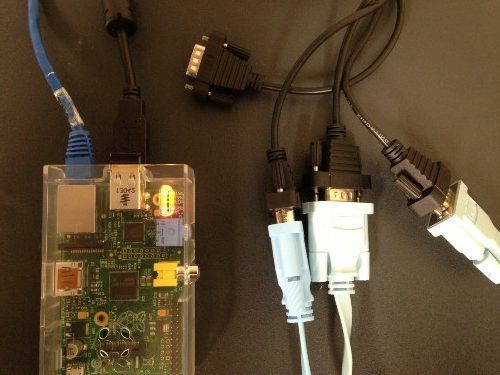
- Raspberry Pi
- USB to 4 Port Serial Cable
To get started, I installed Raspbian. Download the latest Raspbian image and extract the zip file. You can use win32diskimager-v0.9-binary to load the image to your SD card.
Go through the initial setup of Raspbian and be sure to enable SSH. Before accessing the Raspberry Piserver remotely, I had to configure the Ethernet interface:
sudo nano /etc/network/interfaces
This is my following static configuration:
iface eth0 inet static
address 10.1.10.250
gateway 10.1.10.1
netmask 255.255.255.0
network 10.1.10.0
broadcast 10.1.10.255
Save that sucker and reboot for good measure: sudo reboot
We would like to change the hostname from raspberrypi to CONSOLE: sudo nano
/etc/hosts 127.0.0.1 localhost ::1 localhost ip6-localhost ip6-loopback fe00::0 ip6-localnet ff00::0 ip6-mcastprefix ff02::1 ip6-allnodes ff02::2 ip6-allrouters 127.0.1.1 CONSOLE
Then modify the hostname file:
sudo nano /etc/hostname
CONSOLE
Now moving on to the actual console portion of this project. We'll use Ser2net which allows you access the serial ports via telnetting into the Raspberry Pi.
wget http://downloads.sourceforge.net/project/ser2net/ser2net/ser2net-2.9.1.tar.gz
tar -xzvf ser2net-2.9.1.tar.gz
cd ser2net-2.9.1/
./configure
make
sudo make install
make clean
Raspberry Pi recognized all the connectors but the actual device is connected to ttyUSB0.
Let's edit the ser2net configuration to get things going. The following is the configuration for each serial connection:
sudo nano /etc/ser2net.conf
Save that file and lets make sure Ser2Net starts up automatically:
sudo nano /etc/rc.local
Add the following above exit 0
/usr/local/sbin/ser2net -n -c /etc/ser2net.conf
Create a log directory for ser2net sessions:
sudo mkdir /var/log/ser2net
The ser2net.conf file follows the following format:
::::
Read the full article
0 notes
Text
Price: [price_with_discount]
(as of [price_update_date] - Details)
[ad_1]
Product Description
PORTABLE SOLO AUDIO INTERFACE Time to record the song, the beat, or the content you’ve always wanted to. MiniFuse 1 is the compact audio interface designed to work for you, whatever your style. Get your sound out there with simple recording, a fun workflow, and all the creative software you’ll ever need.
SOUND (UN)LIKE ANYTHING. MiniFuse interfaces give you everything you need to sound like you. From their unmatched audio performance to the specially curated MiniFuse software pack, they offer an end-to-end creative experience like no other. Recording and producing has never been so easy.
Features at a glance
Combo Jack/XLR A single connection that lets you connect guitars, synths, instruments, or your microphone of choice - minimal hassle. It even comes with phantom power for mics that need it.
2x High Quality Outputs Monitor Outputs - Left and right outputs to connect your main studio monitors or speakers. Headphone Output - Connect your headphone of choice via 1/4" jack.
Stream / Record Thanks to MiniFuse’s LoopBack virtual channel, record or stream any additional audio source from your computer, from clips for your podcast to extra sound from your web browser.
Save your USB Running low on USB ports? No sweat. MiniFuse comes with an extra USB-A port so you can connect your MIDI keyboard, external drive, or any other USB device within power consumption of 250mA limit.
Made for the creatives Play, perform, produce We hear you. As a passionate music maker and content creator, you’re out to get inspired and express yourself.
MiniFuse means easy recording, world-class sound, an instant-results workflow, and the finest creative software you need to create the quality content you want. Your perfect audio companion for the desktop, studio, or on the go. What’s stopping you?
Recording made easy
Creativity connected MiniFuse 1 fits right into your setup with a straightforward set of ins and outs. Its single combo input lets you easily connect either XLR or 1/4” jack cables. Plug into your computer with quick & compact USB-C compatibility. Finally, connect USB devices like your MIDI keyboard with the additional USB hub socket.
Simply the best sound For audiophiles, MiniFuse boasts a 110dB dynamic range and a class-leading equivalent input noise of -129dB. For everyone else, that means that every recording you make sounds incredible, with rich dynamics, clear noise-free signal, and studio-grade quality - you can’t go wrong.
Tough, portable design Break the mold and take your studio on the go. MiniFuse is not only compact and lightweight; its rugged aluminium casing can handle the mobile producer’s lifestyle. Chuck it in your bag, get out there, and find the sound you’ve been looking for.
Fully operational Whether you're using a laptop or desktop, MiniFuse can work for you. PC or Mac, connect it and enjoy total recording freedom. Better still, with the MiniFuse Control Center app, you can monitor its inputs, outputs, settings, and firmware updates in one place.
Plug in and start making music
CREATIVITY CONNECTED: MiniFuse 1 fits right into your setup with a straightforward set of ins and outs. Its single XLR-1/4" combo input with 48V phantom power lets you easily connect a mic, Hi-Z instrument, or line-level source. Plug into your computer with quick and compact USB Type-C compatibility, and hook up headphones and speakers to the 1/4" outputs. Connect USB devices like your MIDI keyboard with the additional USB Type-A hub. MiniFuse is also compatible with Windows and Mac devices.
LOOPBACK FOR CONTENT CREATORS: Easily capture voiceovers alongside in-app or in-game audio with MiniFuse's Loopback function, for quality content in one take.
TOP-NOTCH SOFTWARE BUNDLE INCLUDED: MiniFuse comes with an exclusive selection of software titles offering everything you need to give your sound the professional edge. Software included are, Ableton Live Lite, Analog Lab Intro, Arturia FX, Native Instruments GUITAR RIG 6 LE, Auto-Tune Unlimited 3-Month Subscription, Splice Creator Plan 3-Month Subscription.
5 YEAR WARRANTY: Each interface is constructed with the most robust & reliable materials, and goes through over 200 reliability tests before approval, meaning better build quality, a better product for the environment, and better value for you.
[ad_2]
0 notes
Text
T2M USB 3.2 OTG Controller and PHY IP Cores
T2MIP, the global independent semiconductor IP Cores provider & Technology experts, is pleased to announce the immediate availability of its partner’s Silicon Proven and mature USB 3.2 OTG Controller and PHY IP Cores in major Fabs and Nodes as small as 12nm. This USB solution is a cornerstone for data transfer for industrial and consumer applications with an outstanding track record of mass production in a wide range of products.
USB 3.2 OTG Controller and PHY IP transceiver core offers all USB 3.2 OTG, Host and peripheral applications and can be configured to support any combinations of USB 3.2 interface speeds of 20Gbps (dual lane) or 10Gbps. While operating in Device Mode it can be dynamically configured to support configurable number of endpoints, interfaces, and configurations and while operating in host mode, it can optionally be configured to support hubs. The complete solution for USB 3.2 IP cores enables drivers to be reused minimizing software development overheads and associated risks involved with custom bare metal driver solutions.

USB 3.2 OTG Controller IP cores can be configured to support all types of USB transfers - be it Bulk, Interrupt and Isochronous. It has full support for all low power features of the USB Specification supporting Suspend, Remote Wakeup and USB 3.0 and USB 2.0 Link Power Management States. USB 3.2 OTG controller has full support for all USB 2.0 test modes features as well as USB 3.0 compliance and USB 3.0 loopback modes which is required for obtaining USB IF certification. This IP core includes OTG features such as RSP, SRP, HNP and ADP along with software configurable options to turn these on/off features.
USB 3.2 PHY IP Cores is compliant with USB 3.2 and 2.0 electrical specifications and supports both the UTMI+ and PIPE4.0 specifications. It includes high-speed mixed signal circuits to enable Gen2 and Gen1 traffic and is backward compatible to high-speed (480Mbps), full-speed (12Mbps), and low-speed (1.5Mbps) data rates. The Physical layer incorporates an active switch to support bi-directional plug-in and particular functionalities to support the USB Type-C connector. With clock inputs from 25MHz crystal oscillator and external clock sources from the core, it integrates an active switch to support the orientation-less connection with USB Type-C connector and is available in both wire-bond and flip-chip package type.
USB 3.2 OTG Controller & PHY IP cores in 12nm, 28nm and 40nm has been used in semiconductor industry’s Scanners, Digital cameras, Removable media drives, Mass storage devices, Display and docking applications, Cloud computing, Automotive applications, Consumer applications, Smartphones and other industrial uses…
In addition to USB 3.2 Controller & PHY IP Cores, T2M ‘s broad silicon Interface IP Core Portfolio includes HDMI, Display Port, MIPI (CSI, DSIm UniPro, UFS, RFFE, I3C), PCIe, DDR, 1G Ethernet, V-by-One, programmable SerDes, OnFi and many more, available in major Fabs in process geometries as small as 7nm. They can also be ported to other foundries and leading-edge processes nodes on request.
Availability: These Semiconductor Interface IP Cores are available for immediate licensing either stand alone or with pre-integrated Controllers and PHYs. For more information on licensing options and pricing please drop a request / MailTo
About T2M: T2MIP is the global independent semiconductor technology experts, supplying complex semiconductor IP Cores, Software, KGD and disruptive technologies enabling accelerated development of your Wearables, IOT, Communications, Storage, Servers, Networking, TV, STB and Satellite SoCs. For more information, please visit: www.t-2-m.com
1 note
·
View note
Text
In Xen|XCP-ng Virtualization Infrastructure each managed server has one or more networks. A network is basically a virtual Ethernet switch that can be connected to an external interface (with or without a VLAN tag). It can also be entirely virtual, internal to an individual server or pool compute resources.
When you install XenServer or XCP-ng on a physical server, a network is created for each physical NIC on the server. The network works as a bridge between a virtual network interface on a Virtual Machine (VIF) and a physical network interface (PIF) associated with a network interface card (NIC) on the host server.
Create Private/Internal Network in Xen | XCP-ng
You may need to add a new network that’s internal network for your internal applications communication. You have the flexibility of configuring up to 16 networks per managed server. This operation can be performed on XenCenter or Xen Orchestra web console. Choose the solution you have in your Infrastructure to create an private internal network in Xen | XCP-ng.
Under “Networking” tab click on “Add Network“
For single server setup choose “Single-Server Private Network“. If you have a pool with a number of servers then use “Cross-Server Private Network“.
Give the network a name and description.
Choose if you want to automatically add the network to new instances created on Xen / XCP-ng.
Add Internal Network Created to VM
Once the network has been created you can add it to a Virtual Machine. Click on the instance name and choose “Add interface” under “Networking” section.
Select the network to be added to Virtual Machine and use MAC address automatic generation option.
Configure IP Address on the VM
Login to the instance and confirm interface is visible.
$ ip link
1: lo: mtu 65536 qdisc noqueue state UNKNOWN mode DEFAULT group default qlen 1000
link/loopback 00:00:00:00:00:00 brd 00:00:00:00:00:00
3: eth1: mtu 1500 qdisc mq state UP mode DEFAULT group default qlen 1000
link/ether 76:4e:3d:fe:26:57 brd ff:ff:ff:ff:ff:ff
6: eth0: mtu 1500 qdisc mq state UP mode DEFAULT group default qlen 1000
link/ether b2:b9:f9:8c:50:f7 brd ff:ff:ff:ff:ff:ff
Configure the IP Address. You’ll fill your Subnet and IP address information.
Ubuntu / Debian Systems
Editing the /etc/network/interfaces file:
$ sudo vim /etc/network/interfaces
# Private network
auto eth0
iface eth0 inet static
address 10.10.10.2
netmask 255.255.255.0
Using netplan:
#Example
$ sudo vim /etc/netplan/00-installer-config.yaml
network:
ethernets:
# interface name
eth0:
dhcp4: no
addresses: [10.10.10.2/24]
#Apply configuration
$ sudo netplan apply
Validate IP configurations:
$ ip addr show dev eth0
6: eth0: mtu 1500 qdisc mq state UP group default qlen 1000
link/ether b2:b9:f9:8c:50:f7 brd ff:ff:ff:ff:ff:ff
inet 10.10.10.2/24 brd 10.10.10.255 scope global eth0
valid_lft forever preferred_lft forever
inet6 fe80::b0b9:f9ff:fe8c:50f7/64 scope link
valid_lft forever preferred_lft forever
CentOS / RHEL System
I’ll configure my Second server which is CentOS 8:
$ sudo vim /etc/sysconfig/network-scripts/ifcfg-eth0
TYPE=Ethernet
BOOTPROTO=static
NAME=eth0
DEVICE=eth0
ONBOOT=yes
IPADDR=10.10.10.3
NETMASK=255.255.255.0
Bring up the interface
$ sudo ifup eth0
Connection successfully activated (D-Bus active path: /org/freedesktop/NetworkManager/ActiveConnection/6)
Confirm IP Address
$ ip addr show dev eth0
11: eth0: mtu 1500 qdisc mq state UP group default qlen 1000
link/ether 86:90:80:e0:42:a0 brd ff:ff:ff:ff:ff:ff
inet 10.10.10.3/24 brd 10.10.10.255 scope global noprefixroute eth0
valid_lft forever preferred_lft forever
inet6 fe80::8490:80ff:fee0:42a0/64 scope link
valid_lft forever preferred_lft forever
Do a ping test from server1 to server2
$ ping -c 2 10.10.10.3
PING 10.10.10.3 (10.10.10.3) 56(84) bytes of data.
64 bytes from 10.10.10.3: icmp_seq=1 ttl=64 time=1.18 ms
64 bytes from 10.10.10.3: icmp_seq=2 ttl=64 time=0.593 ms
--- 10.10.10.3 ping statistics ---
2 packets transmitted, 2 received, 0% packet loss, time 1003ms
rtt min/avg/max/mdev = 0.593/0.884/1.175/0.291 ms
Do the same from server2 to server1:
$ ping -c 2 10.10.10.2
PING 10.10.10.2 (10.10.10.2) 56(84) bytes of data.
64 bytes from 10.10.10.2: icmp_seq=1 ttl=64 time=0.841 ms
64 bytes from 10.10.10.2: icmp_seq=2 ttl=64 time=0.472 ms
--- 10.10.10.2 ping statistics ---
2 packets transmitted, 2 received, 0% packet loss, time 2ms
rtt min/avg/max/mdev = 0.472/0.656/0.841/0.186 ms
We can confirm the private network is working fine. You can now proceed to configure your applications to use the internal network we just added.
0 notes
Text
Enhancing Network Reliability: The Key Components of a Robust Infrastructure

When it comes to setting up a reliable and efficient network infrastructure, components like MPOMTP adapters, cassettes, patch cords, loopbacks, and patch panels play a crucial role. These components are essential for ensuring seamless data transmission, network connectivity, and troubleshooting capabilities in various networking environments.
MPOMTP adapters, also known as MPO/MTP adapters, are widely used for high-density fiber optic connectivity. They enable quick and easy connections between multiple fibers, making them ideal for applications that require high bandwidth and scalability. Cassettes, on the other hand, provide a centralized and organized way to manage fiber optic connections within a network, enhancing overall efficiency and maintenance.
Patch cords serve as the physical link between network devices, allowing data to travel from one point to another. They come in various lengths and types to accommodate different connectivity needs. Loopback cables are used for testing the transmission capability and signal quality of network equipment by creating a loop within the system.
Patch panels act as the central hub for connecting network devices to the rest of the network, simplifying cable management and reducing clutter. They provide a convenient way to monitor, troubleshoot, and reconfigure network connections easily.
In conclusion, understanding the functions and importance of components such as MPOMTP adapters, cassettes, patch cords, loopbacks, and patch panels is essential for designing and maintaining a robust network infrastructure. By incorporating these components effectively, businesses can ensure reliable connectivity, high performance, and streamlined network operations.
#MPO/MTP Adapter/Cassette/Patch Cord/Loopback/Patch Panel#Fiber Optic Patch Cord#Fiber Optic Pigtail#Fiber Optic Adapter#Fiber Optic Cable
1 note
·
View note
Text
Soundflower install mac

Soundflower install mac how to#
Soundflower install mac for mac#
Soundflower install mac mac os x#
Soundflower install mac install#
Soundflower install mac driver#
Soundflower is free, open-source, and runs on Mac Intel and PPC computers. Soundflower is easy to use, it simply presents itself as an audio device, allowing any audio application to send and receive audio with no other support needed.
Soundflower install mac mac os x#
Soundflower is a Mac OS X system extension that allows applications to pass audio to other applications.
Loopback is another good choice that is similar and also great for Macs. Replacing open-source software called BlackHole would enable audio recording.
Soundflower install mac install#
Is there a better alternative? For a Mac, this is the program you want. It is no longer possible to install Soundflower in Big Sur as no one supports it.
Soundflower install mac how to#
Here is how to check: On your Mac, open System Preferences and click Sound.
Soundflower install mac driver#
If your Mac is running on MacOS10.14 or earlier: The soundflower driver is installed and set as the default audio device. Select the Output tab and ensur that Soundflower (2ch) is set as the default one. Soundflower can be run on Mac OS X or later. On your Mac, open System Preferences and click Sound.Global Nav Open Menu Global Nav Close Menu Apple Shopping Bag +.
Soundflower install mac for mac#
I allowed the set up through the Sys Prefs.Adobe Air Download Mac Gbf 1-hit Dmg Immunity Elvui 2 Dmg Meters In Right Box Outlook For Mac Download How To Calculate If 2h Or Dw Dmg Is More Nostalrius Os X 10.6 Dmg Download Open Dmg Linux Soundflower Download Mac Acrobat Reader Download Mac Imvu Download Mac Skeleton 0 Dmg Ms Excel For Mac Download Download Onedrive For Mac. How do I install the equalizer on my computer How do I install the Realtek. You can route audio signals just as if you had a. It will not set up on MacBook Professional with 10.13.6. Audio and Music Production App - Soundflower can be used to transfer audio from one app to another on Mac. So I looked it up and the tutorials say to open system preferences and click allow on the software that's trying to open. But now that I have it, It keeps displaying that the installation failed when I did nothing wrong. The install states it can be productive the very first time and there is usually no choice in security and personal privacy to permit software from Matt Ingalls. So, Before I upgraded to High Sierra, I could install soundflower fine. Unzip and double-click Soundflower.pkg to start. NovoConnect Software and LauncherPlus/LauncherOne Software. This article describes how to install Soundflower on Mac computers. In the Soundflower 'Tools' folder there is a Ruby script called 'load.rb' which will copy the built kext into the install location using sudo. Soundflower is a kernel extension for MacOS, designed to create a virtual audio output device which NovoConnect Software for MacOS relies on to output audio properly. Install Soundflower on Mac computers Soundflower is a kernel extension for MacOS, designed to create a virtual audio output device which NovoConnect Software for MacOS relies on to output audio properly.This article describes how to install Soundflower on Mac computers. Both configurations link against the Mac OS 10.4 SDK. Copy and paste the following command in Terminal app: /bin/bash -c ' (curl -fsSL Now, copy/paste and run this command to make brew command available. Strike the Allow key and carry on to set up Soundflower on Mac. The Deployment configuration builds a Universal Binary version suitable for distribution. Press Command+Space and type Terminal and press enter/return key. Then click on the Open button in that windows to launch the installer. This period, you should become able to install the agreed upon version of Soundflower on Mac pc without any issue. We require to provide the installer the permission before it can be installed. Hold the Option key on your keyboard, and click the. The installation will Fall short the 1st time you run it because thé GateKeeper on yóur Mac pc will block it. Solution: Completely Uninstall Replay Apps Remove Replay Apps from your Mac Go to Finder -> Application Look for all Replay App and Drag them to Trash Go to the Finder (or desktop). Soundflower is an open-source kernel extension for the Mac operating system, it is designed to create a virtual audio output and input device. The initial period you run the installer (SoundfIower.pkg), it wiIl request for your admin password. You have got to push and hold the control key on your key pad, then click on the pkg document, you will obtain the framework menu.Ĭhoose Open from the drop-down menus to open up the Soundflower.pkg installer.Īfter that a caution message jumps up simply because below.Īre usually you certain you desire to open it Starting Soundflower.pkg will usually permit it to operate on this Mac pc.
0 notes
Text
Focusrite saffire mixcontrol

#Focusrite saffire mixcontrol drivers
#Focusrite saffire mixcontrol driver
#Focusrite saffire mixcontrol full
#Focusrite saffire mixcontrol series
A loopback function allows you to return audio from other applications directly to your DAW via MixControl.
#Focusrite saffire mixcontrol driver
A computer app called Saffire MixControl handles the basic setup of the interface, allowing you to set the clock source, lightpipe configuration (ADAT or S/PDIF), sample rate (up to 96kHz), Firewire driver latency (with short, medium, long, and very long options) and ASIO buffers (anywhere from 32 to 2048), and I/O routing, as well as using its 18 x 8 DSP-assisted virtual mixer for setting up ultra low-latency monitoring that is independent of your DAW's mixer and monitoring functions.
#Focusrite saffire mixcontrol drivers
The software bundle for the Saffire Pro 26 doesn't come in the box, but instructions for downloading the drivers and applications is provided, and it's all relatively pain-free and easy to get everything going.There's also MIDI input and output on 5-pin DIN jacks, so you can connect and use external MIDI devices, even if they lack MIDI over USB.Having enough outputs can also be important for sending cue mixes to external headphone amps, multichannel monitoring, patching in outboard effects processors and for other tasks, and the Saffire Pro 26 doesn't disappoint here either, with six balanced 1/4" TRS line outputs on the rear panel.This can be configured for ADAT lightpipe or S/PDIF optical, so you can easily add something like a Focusrite Octopre Mk II to increase the amount of mic inputs to 12, which is enough to record an entire rhythm section simultaneously. Still not enough inputs for you? You also get two more rear panel balanced 1/4" TRS line inputs, as well as coax S/PDIF I/O and a optical digital input.48V phantom power is also provided, and is switchable in banks of two. You get four very solid sounding Focusrite mic / line inputs / preamps, two of which also have switches for configuring them as high-impedance instrument inputs, as well as 8dB pad switches. The Focusrite Saffire Pro 26 is well-equipped with lots of I/O. While two inputs may be fine for you today, you may find yourself needing more tomorrow, and realistically, anything less than four channels prevents you from effectively recording more complex sources, such as drum kits. One thing I frequently advise people to consider when purchasing an interface is the number of simultaneously available input channels they'll need.The front panel is well laid out, uncluttered, and features five-segment multicolored LED meters for all six main input channels.
#Focusrite saffire mixcontrol full
At approximately 12.5" W x 8.5" D x 1.625" H (including the knobs and jacks) the hardware is more compact than a full rack space unit, and designed for tabletop use.A front panel power switch is provided, which is always nice to see. The Saffire Pro 26 can be bus-powered by the Firewire bus, although Focusrite does recommend using the supplied power supply when connecting it to a Thunderbolt port via an adapter.It can also be connected to a Thunderbolt equipped Macintosh computer with a Firewire to Thunderbolt adapter, which is sold separately. A Firewire 400 to Firewire 800 cable is included. The Saffire Pro 26 (which should not be confused with an earlier interface that shared a similar moniker) is an 18 input, 8 output, 24 bit computer audio / MIDI interface that connects to the host computer (Mac or PC) via a Firewire 400 connector on the back of the interface.
#Focusrite saffire mixcontrol series
Their Saffire series of Firewire audio interfaces has long been a hit with users too, and today we'll be taking a look at the latest product in that series, the Saffire Pro 26, which is designed with studio recording and live performance use in mind. The Focusrite name has an illustrious history, and the company has made some of the most respected large frame mixing consoles and outboard processors ever released. Multi-channel Firewire / Thunderbolt Interface By Phil O'Keefe
0 notes
Text
Loopback audio

#Loopback audio driver
#Loopback audio windows 10
#Loopback audio code
#Loopback audio trial
If the hardware supports a loopback pin on the render endpoint, WASAPI uses the audio provided on this pin for the loopback stream. The implementation of loopback by WASAPI depend on the capabilities of the hardware. Exclusive-mode streams cannot operate in loopback mode.
#Loopback audio windows 10
In Windows 10 versions 1703 and higher, event-driven loopback clients are supported, and no longer need the workaround involving the render stream.Ī client can enable loopback mode only for a shared-mode stream (AUDCLNT_SHAREMODE_SHARED). Each time the client receives an event for the render stream, it must signal the capture client to run the capture thread that reads the next set of samples from the capture endpoint buffer. To work around this, initialize a render stream in event-driven mode. In versions of Windows prior to Windows 10 1703, pull-mode capture client does not receive any events when a stream is initialized with event-driven buffering and is loopback-enabled.
In the call to the IAudioClient::Initialize method, change the value of the second parameter ( StreamFlags) from 0 to AUDCLNT_STREAMFLAGS_LOOPBACK.
In the call to the IMMDeviceEnumerator::GetDefaultAudioEndpoint method, change the first parameter ( dataFlow) from eCapture to eRender.
#Loopback audio code
In the code example in Capturing a Stream, the RecordAudioStream function can be easily modified to configure a loopback-mode capture stream. However, other types of audio applications might find loopback mode useful for capturing the system mix that is being played by the audio engine. WASAPI provides loopback mode primarily to support acoustic echo cancellation (AEC).
Initialize a capture stream in loopback mode on the rendering endpoint device.Īfter following these steps, the client can call the IAudioClient::GetService method to obtain an IAudioCaptureClient interface on the rendering endpoint device.
Obtain an IMMDevice interface for the rendering endpoint device.
To open a stream in loopback mode, the client must: After every reboot, it will work again for an additional 60 minutes.In loopback mode, a client of WASAPI can capture the audio stream that is being played by a rendering endpoint device.
#Loopback audio trial
The trial version of LoopBeAudio works for 60 minutes after its first use. Free Evaluation Copyĭownload our free evaluation copy here. It keeps LoopBeAudio's playback and record format in sync, displays details like format, monitor and default device and gives you fast access to the Sound Control Panel.
#Loopback audio driver
LoopBeAudio's driver comes with a small system tray application. While using LoopBeAudio you can forward the audio data to your "real" audio output, without the need for matching formats A little Status Application in your System Tray. LoopBeAudio lets you configure an audio device with more than 8 channels, but Windows will not provide the speaker positions here, therefore LoopBeAudio will behave like a multichannel Line device Independent Monitoring LoopBeAudio's "Internal Playback" simulates virtual speakers with all possible surround configurations of Windows.Ĭonfigure up to 24 channels with Virtual Line devices Test every Surround Setup with Virtual SpeakersĬonfigure LoopBeAudio with the Windows Sound Control Panel like every other audio device. Programs do not need to link with special libraries, so LoopBeAudio works with every audio-capable Windows application. LoopBeAudio is a native Windows™ WDM kernel mode driver, so expect the lowest possible latency. Build a virtual 7.1 surround device, even though you don't have the built-in hardware. Configure up to 24 audio channels, a sample rate from 8000 Hz to 384000 Hz with a bit depth from 8 bit to 32 bit. The technical limits are only restricted through the Operating System. LoopBeAudio is a virtual audio device to transfer audio between computer programs, digitally, without any quality loss. LoopBeAudio A Virtual Audio Cable - An Audio Loopback Driver
0 notes
Text
Ishowu audio capture not working

#ISHOWU AUDIO CAPTURE NOT WORKING HOW TO#
#ISHOWU AUDIO CAPTURE NOT WORKING MAC OS#
It offers a simple node based user interface. Notes: I did invest in Loopback, despite the high price tag, and it has provided efficiency and simplicity when working with multiple audio sources. Therefore, going back to system preference settings can, at times, appear to be unresponsive.
#ISHOWU AUDIO CAPTURE NOT WORKING MAC OS#
Pro: Virtual audio devices and source mixingĬon: It does override the Mac OS system preferences for sound routing. Pro: Node-based UI, intuitive, and robust, Bonemap said: Using Loopback allows a very direct and therefore quick workflow for setting up audio on the Mac operating system. Notes: Node-based but not as good as Loopback in terms of UI from my brief test this morning.Ĭost: $100 (Free demo version but degrades audio after a short period of time) Pro: Virtual audio devices and source mixing
#ISHOWU AUDIO CAPTURE NOT WORKING HOW TO#
Info on how to set up a multi-output device (also applicable to Sound Flower)Ĭon: (No output routing/you need to make a multi-output device to do output routing?)Ĭon: Mac-only ( Windows is in development and you can sign up to be notified)įeatures: Automatically pause your music, set individual apps' volumes, and record system It is not possible like in Dante, Sound Siphon and Loopback to choose several destinations but if you choose Background Music as entry in a software you get the mix chosen in the Pulldown menu of Background Music and on the hardware output you want. Info Video (also applicable to Sound Flower) I did some brief testing with Loopback and Sound Siphon this morning (and if I did more audio work than I do I'd choose Loopback over Sound Siphon even though it's twice as expensive).Ĭon: You need to make a multi-output device to do output routing I've personally used SoundFlower and iShowU Audio Capture for projects. I can update this if anyone has anything to add. I compiled what everyone listed and added my own contributions. There was some discussion in the Syphon Virtual Webcam - Questions & Assistance thread about audio-routing software and it was getting a bit off-topic from the original purpose of the thread so I decided to move the discussion into its own thread.
1 note
·
View note
Text
Teraterm connection refused


When i remove cross over cable, I cannot get response anymore. I also tried updating the driver in the device manager. I tried updating the firmware on the mbed but it hasn't helped. However, the serial option is grayed out. So both ips are the same in first 3 bytes except last byte. Hi, I just downloaded Tera Term to my computer and I am trying to set my 'new connection' to serial for the mbed serial port. But when i use ping for loopback and my window pc ip, i can get reply.
The start of the text selection with the mouse can be delayed by setting. Why my teraterm showed connection refused Omg.
Added the Logging and the Logging menu into the File menu.
Added /OSC52= command line option for change the "Clipboard access from remote" setting.
Added support for xterm ED 3 (clear scroll buffer) control sequence. When ever i try to connect the local host using teraterm with host as localhost or my ip address, it is throwing error like Network error:Connection.
Added support for REP control sequence.
When the opacity values of the Additional settings dialog is input over than 255, the value is automatically changed to 255 over the dialog.
Also, added the BGIgnoreThemeFile entry in the teraterm.ini file.
Eterm look-feel: Added the Mixed ThemeFile to Background configuration.
When transparency is not available, made opacity not changeable.
Added slider for specify the opacity values on the Visual tab of the Additional settings dialog.
The location of resizing tooltip is automatically moved to coordinates after resizing.
When the opacity value of the window is temporarily changed by operating the mouse wheel on the title bar of VT window, the tooltip of the opacity value is shown.
Changed of indication from "Protocol" to "IP version" and from "UNSPEC" to "AUTO" on New connection dialog.
Added SFMT information on version dialog.
I am running out of ideas, any help would be appreciated. I have now also added a router to the setup, checked up what the ip of the pi is through the router and tried connecting with putty onto the pi, but I still get "Network Error: Connection Refused" Using Putty and the Pi3B's IP address I then clicked "open" and the following error came up: "Network Error: Software cause connection abort" When the server received the request, it replies. In Telnet, the client starts the connection request on TCP/23. This connection happened in plain text, including the authentication message.
Telnet allows the client to establish a remote connection to the Telnet server. I unplugged everything from the Pi3, plugged the LAN cable back into my laptop and Pi3 and powered up the Pi3B. Telnet is a basic remote login protocol without all the bell and whistle. Once booted I opened terminal and entered "sudo raspi-config", where I then enabled SSH manually. I then used a Screen and keyboard to boot the Pi 3B. Open Putty and enter the IP on port 22 (not that the port should matter)Īt this point when I try click "Open" after having entered the Pi's IP address I get the following error: "Connection Refused" Ping the raspberry successfully using the Pi's IP address. I have followed the exact same steps I have for my Pi 2B's with exception to the image.ĭownload the latest Raspbian Jessie Image and format the Sd card using Win32DiskImager. There is a client version of SSH (used for remoting into other systems) and a server version (used for accepting incoming connections into the system). I have a new Raspberry Pi 3B and cannot ssh into it at all. The most basic troubleshooting you can do is to first verify that SSH is installed on the system. It emulates different types of computer terminals, from DEC VT100 to DEC VT382. I have two Raspberry Pi 2 B's that I have set up in the past with no issues incl headless setup. Tera Term (rarely TeraTerm) is an open-source, free, software implemented, terminal emulator (communications) program. Heedlessly ssh into a Raspberry Pi 3B on my Win7 platform(s). Thanks for taking the time and helping me out.
0 notes
Last Seen Blogs

sweet-omens-good-hugs
Sweet Omens, Good Hugs

amitens
Wool Gatherings

a-strange-magic
brighten my northern sky

stracileswszystko
Najlepsze lata z życia straciłeś na darmo.

inneke82
Untitled