#10 points for what? wdk. you decide
Text
love this animal. monster scarlet
#bug fables#monsieur scarlet#stuff i made tag#we know that's not how monsieur is pronounced it's just a funny ok#also you get 10 points if you know the song he's singing in the washing-a-dress drawing#10 points for what? wdk. you decide#this is what happens when we read things. sudden burst of inspiration to draw one billion draculas
43 notes
·
View notes
Text
Microchip Sound Cards & Media Devices Driver Download

60 Seconds Voice Recording Module, DIY Sound Recording Greeting Card Chip, Recordable Light Voice Sound Chip Module Replacement 3.9 out of 5 stars 22 $10.99 $ 10. The IBM Music Feature card is one of the original sound cards. This fairly expensive card includes an eight-voice stereo synthesizer and a complete MIDI interface. The heart of this card is the Yamaha YM-2164 sound chip, which can also be found in the Yamaha FB-01 MIDI Expander. Aug 08, 2019 The sound card in your computer is responsible for controlling and processing the input and output of all audio on your machine. If you’re having problems with audio on your computer, or have recently installed a new sound card, you can verify that the sound card is being detected by Windows. Method 1 Windows 8.
> Sound button
> sound book
prevnext
Introduction:Item:voice recordable musical chipMaterial:plastic & metalSize:30*40mm/customizedSwitch:Button/magnetic switch/Slide switchSound length:10-1800s/customize
Custom programmable Recording Sound chip for Greeting Card
Product description
Item
voice recordable musical Sound chip
Material
plastic & metal
Size
30*40mm/customized
Switch
Button/magnetic switch/Slide switch
Sound length
10-1800s/customize
Iife time
500 times more or less
Packing
EPE packaging and outside carton
Certification
CE,RoHS,FCC.
Power:
3*AG13/AG10
Application
recordable cards and sound toys etc
OEM or ODM
Welcome
MOQ
1000pcs
Picture
Two buttons voice Recording chip
Packaging & Delivery
Packing details
EPE and outside cartoon or customized
Shipping details
By regular air/ By sea/ By international express
Delivery detail
15-25 days
How to record by yourself
1.Pull out the insulation slices
2.Record your own message by pressing button.
3.Press another button play the message.
Ways to pre-record
We offer the musical chip can be designed to connected with a microphone / a usb cable or a TF card.
1. Microphone
A record button would be designed to record your own voice or sound source. Broadcast quality depends on entry of audio quality and environmental noise.
2. IC
Send us your sound source,we insert the sound source into IC.
3. USB
Uploaded the sound source to your computer(sound source can recorded by your cell-phone), then copy to your removable disk directly. The sound duration can be customized.
4. TF card
Download the music to TF card, and insert the card to module, then the module will play music which inside the TF card.
Why choose us:
1. We are the manufacturer of customized sound & luminous module, electronic gifts & toys and so on.
2. Our company develop and design customized products independently, which with high quality and reasonable price.
3. Professional team has more experience with more than 10 years development.
4. Skillful workers ensure quality and speed.
5. Customer satisfaction is our top priority.
6. Rapid response is our working standard.
Company introduction
Shenzhen Xinditai Electronic Co.,Ltd. Established in 2001, We are professional manufacturer of sound & luminous modules, and expert custom solutions provider of sound&luminous modules with high quality and reasonable price in Shenzhen of China Mainland. We have a series of products from musical chip, recording sound modules, voice recognition module,USB audio module, download sound chip, recordable greeting card, squeeze box music, led flashing modules for toys, gifts and cards to Bluetooth player, etc.
FAQ
Q: Are you a factory or a trading company?
A: We have own company and factory that we can provide perfect OEM and after-sale service.
Q: Sample time and price?
A: Will according to your design about 5-7 days.
Q: What is your MOQ and delivery time?
A: MOQ is 1000 pcs. 10-15 days for minimum order quantity.
Q: How can I pay my order?
A: We accept T/T, Western Union paying methods. For those orders less than 1000 USD, we accept PayPal to pay.
Q: Do you have certificate?
A: All of our product has CE, RoHS and FCC certificate.
Contact information
Shenzhen XindiTai Electronics Co., Ltd.
Add: Floor 3-4, No. 12, Lane 1, Nanlian Baolong Community, Longgang Street, Longgang District,Shenzhen,China
Telephone: 0086-755- 8989-1700
0086-755- 8989-1702
Mobile:+0086-157 28259858 (Whatsapp)
A Microchip PIC based USB sound card
INTRODUCTION
The idea for creating a USB sound card based on a PIC came from discussions of other people creating one on the Microchip USB forum. The hardware of the card is based on all Microchip products. The software uses a modified version of the Microchip USB framework which is interrupt driven instead of the traditional polling. The device is a USB composite device. The first device is an implementation of the USB Audio 1.0 interface and the other device is a custom interface based on a HID interface. The purpose of the custom interface is for programming the device serial number, upgrading the firmware, and in the future any other configuration that isn’t supported directly by USB Audio 1.0. In a previous version, WinHTTP was oringally used. After testing the card for awhile, I decided it's better to not require drivers for the card especially since the HID/WinUSB interface is rarely used.
The sound card runs at a sample rate of 48KHz, 32KHz or 24KHz selectable by the OS with 12 bits per sample. The quality approaches commercial grade as the sample rate is higher then CDs. 44.1KHz was not implemented due to the difficultly and additional processing overhead. The sample rates that were implemented are all a multiple of the 1ms USB frame meaning each frame sends the same amount of data. 44.1KHz requires the card to handle different amounts of data each frame requiring more advanced buffering and synchronization techniques and more processing power. Microsoft Windows automatically resamples the 44.1KHz audio found on CDs to 48KHz.
USB Audio Streamer V1.2
HARDWARE
Click for enlarge
Schematic for USB Audio Streamer V1.2
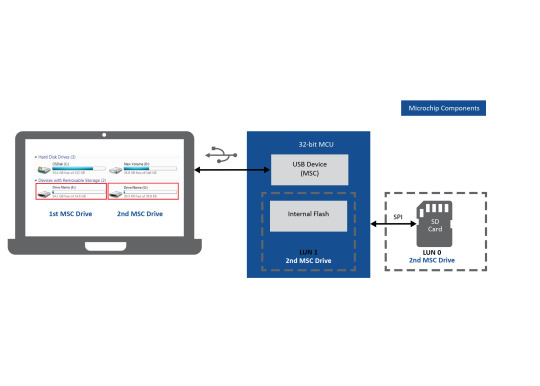
The hardware for the sound card is based on the Microchip PIC18F2550 USB processor. The processor is clocked at 48MHz which is the maximum rate for this processor and is also a multiple of the audio sample rate. The microcontroller is connected via the SPI port to duel Microchip MCP4822 12bit D/A converters. Volume control is implemented by the Microchip MCP41010 variable res-- ders are controlled via SPI by the microcontroller via a dedicated bit-banged SPI port. The purpose of using a separate port is so that volume control can run inside the processor at a different priority level then sample output. The Microchip MCP6022 op-amp is used as an output driver.
The MCP6022 op-amp has an output drive capacity large enough to power a pair of cheap headphones without much distortion. The resistance of my headphones is approximately 25ohms. The op-amps are not powerful enough to drive speakers which are usually 8 or 4 ohms. The MCP41010 and MCP6022 can output near rail to rail voltage although some nonlinear effects can be heard if the volume is too loud or the signal is near the minimum or maximum. Since USB has a single rail 5V power supply, the sound card only uses a positive rail instead of a traditional duel rail system which is how standard 16bit PCM is encoded. As a result, the signal needs to be biased in software to 2.5V.
One terminal of the MCP41010 is connected to the signal for that channel and the other terminal is connected to the midpoint or bias voltage. Previous versions of this sound card connected the second terminal to GND. The advantage of connecting the terminal to the bias is that as the volume is changed, the signal grows or shrinks around the midpoint rather then shifting toward GND. The signal is kept as far away from the rails as possible.
SOFTWARE
The software for USB Audio Streamer is composed of several components. These are the audio card firmware, a C++ library that wraps HID and WinUSB, and a command line utility for flashing. I am giving out the source code as a learning tool for other people. I don’t care what you do with it but I am not responsible for any damage that might happen from using it. NOTE: Improper use of hardware or software may cause serious injury or death.:)
I use Visual Studio 2005 Professional but I have heard that the project will build with Visual Studio Express. To build the project it is necessary to download the latest version of the WDK to get the headers and library files for HID and WinUSB. The default directories in Visual studio need to be modified to point to the directories of these resources in the WDK. If you use Visual Studio Express it's necessary to recreate all the project files and change the default calling convention to _stdcall.
DirectoryFunctionincGeneral Include DirectorybootBoot Loader(Build first)audiostreamSound card firmwareusbdevprogramerProgrammer command line utility(Build last)
Source Code Modules
A trick is used when building the sound card firmware since it is two separate projects that need to be merged together. Build the boot directory first, which is the code responsible for upgrading the firmware. Then build the sound card firmware itself. Before flashing, goto Configure/Settings/Program Loading and clear the option to clear program memory upon loading a new program. After the sound card firmware is build, goto file/import and import the hex file for the boot loader. The two projects will be merged together without any cutting and pasting. At this point, it is OK to flash the PIC. Note the bootloader is only necessary for flashing firmwares without a ICD/Pickit. When debugging actual card functionality, it's ok to leave out the bootloader. This Requires no modifications to the sounce or linker scripts. Simply don't merge the boot loader into the image
SOUND CARD FIRMWARE
The sound card firmware is based on a modified version of the Microchip USB framework. The framework has been collapsed into a single source file with callbacks between the framework and the main code. The framework( in my case it’s more of a library ) has been modified to use interrupts instead of the traditional polling method. Instead of calling USBDriverService in a loop, this function is called whenever the USB interrupt fires. The library is response for handling control requests on endpoint 0. The framework handles standard USB requests and the body code is responsible for handling class specific USB requests nonstandard requests. The body code is responsible for handling I/O on all other endpoints.
USB Audio Streamer is a composite device of a USB Audio 1.0 device and a custom HID interface. With USB Audio 1.0 all of the sample data is transferred through a separate endpoint then control requests. Control requests such as controlling volume is through endpoint 0(the control endpoint.) HID uses it’s own endpoint. Since each function of the card has a separate endpoint, each of the functions can be implemented at a different priority level without preemption problems. The PIC18F2550 has two interrupt priorities plus the main handler. This gives a total of three priorities. Since playing sound data is the most critical function it was given the highest priority. Next comes control endpoint requests which include the standard requests plus Audio 1.0 requests. Since these functions have relatively low timeouts, these were assigned low priority. HID functions are in the main body code because actions such as querying the firmware version, settings the serial number, or flashing the firmware are not time critical at all.
EndpointPriorityFunctionEP 2Interrupt(High)Streams the audio data to the D/A converterEP 0Interrupt(Low)Control Endpoint function and Audio 1.0 requestsEP 1Main(Background)Non standard functions
Endpoints, priorities, and functions of firmware

CORE AUDIO
The low priority interrupt handler performs two functions. The first is to check the ISO endpoint through the SIE for data. If data is available the buffer is passed to the high priority interupt code and next buffer that makes up a cicular queue is returned to the SIE. The buffers are in the USB ram of the PIC so that the data is not copied between buffers. In Audio 1.0, the host always sends exactly the number of samples to fit in a frame which is 196, 128 or 96 bytes depending on the sample rate used.
The second function of the low priority interrupt handler is SOF(start of frame) processing. Upon receiving the SOF, the PIC changes the current play buffer to the next available buffer and starts timer 2 which is the sample clock. Timer 2 is always reset on the SOF to keep the sample clock synchronized when clock drift is present. If the SOF occurs before the current buffer is played, playback is changed to the next buffer. If the SOF occurs after the buffer is finished, the last sample is stretch. Since the clock drift is normally small, most of the time samples are not dropped. The time of the last sample is slightly different. This is not noticeable in the audio and is only barely noticeable when playing SIN waves.
The high priority interrupt is driven off timer 2 and has the function of formating the data in the format required by the converter and loading the D/A converter through the SPI port of the PIC. The samples are converted from 16 bits signed PCM to 12 bit unsigned and the endianess is swapped. After the buffer is finished, timer 2 is stopped so that if the clock of the card is ahead of the host, the last sample is stretched.
AUDIO 1.0 REQUESTS
All Audio 1.0 requests are handled via an extension of the USB framework. The low priority interrupt calls USBDriverService which services the control request. If the request is a standard USB request, the request is handled by the framework. If it isn't, the framework calls back into the main code which examines the request. If the request is recognized, the main code claims the request. If the request is a read request, the main body sets the address of a variable to sent to the host. If it's a write request, a variable is written to but the firmware sets a completion routine to be called at the end of the request.
The card only handles two types of requests which are volume control and sample rate selection. The current value of both of these is stored in a global variable. If the volume is adjusted, new values are loaded into the variable resistors. If the sampling rate is adjusted, a new period is loaded into PR2 for timer 2.
HID REQUESTS AND HOST SOFTWARE
The main body code polls endpoint 1 for custom requests in a loop. If the request is anything other then setting the serial or flashing the firmware, the request is handled in the main body code. Otherwise, the processor is put into a special programming mode. Upon entering this mode, all interrupts are disabled and the USB library is used in the traditional polling mode as program memory blocks are moved from the host. Flashing the microcontroller is reusable code that is used for multiple projects.
The host side consists of a C++ library that wraps HID and a command line C utility for configuring the card. These utilities are used for multiple projects and will be discussed in a separate topic.
TESTING 123...
The USB Audio Streamer uses instrumentation grade analog components so frequency response is not a major concern. The main concern is noise and signal accuracy due to nonlinear properties of the components, jitter, and that the sample clock can drift from the USB SOF clock.
To measure the accuracy, I used Audicity to play 20 second sin tones of various frequencies and recorded the output on a Dell laptop with a built-in 24bit 96KHz Sigmatel sound card. The assumption is that the 24bit sound card is much better then the USB hardware. The output was recorded with Audicity and the spectrum of the signal plotted. The idea is that perfect hardware would have a single peak at the tone’s frequency and nothing elsewhere. The experiment was performed with both the USB Audio Streamer and a commercial 16 bit USB sound card the Turtle Beach Audio Advantage. In all cases, a 48KHz sample rate was used. In the follow graphs, the Audio Streamer is on the left and the Turtle Beach is on the right.
Click for enlarge
Click for enlarge
1KHz SIN
Click for enlarge
Click for enlarge
4KHz SIN
Click for enlarge
Click for enlarge
20KHz SIN
Cards With Sound
As can be seen, the accuracy of both devices decreases as the tone’s frequency is increased. Up to about 12KHz, both devices have approximately the same noise floor. At 12KHz though, the Audio Streamer’s performance begins to rapidly diminish. Both devices are isosynchronous adaptive, but apparently the Turtle Beach has better drift control algorithms. At 20KHz, even the Turtle Beach has noise of -40dB which is not that good. It seems that designing a high quality USB audio device is very difficult even for commercial developers.
Microchip Sound Cards For Kids
Tone FrequencyAudio StreamerTurtle Beach1KHz-50dB-55dB2KHz-50dB-55dB4KHz-45dB-50dB8KHz-40dB-40dB12KHz-35dB-45dB16KHz-30dB-40dB20Hz-25dB-40dB
0 notes
Last Seen Blogs

waitinbythephone
andromeda 🪼

tkd-w
Ql foi???

derekfett
Esteban Horvath

friisans
ಠ_ಠ

peace-2020s-blog
Discourse of peace for all