
openlabpro-blog
Embedded systems, IoT, Online Courses
Specially crafted Learning and Design platform for Embedded Systems, Learn hardware design and firmware development together. Available for ARM, PIC, 8051 and AVR microcontrollers.
13 posts
Don't wanna be here? Send us removal request.
Last Seen Blogs

lightxspinnwr
gcb

jeffbig9c
Sans titre

jcruizphoto
JC Ruiz Photography


kultsipippeli
Tämä voisi olla metsä
Photo
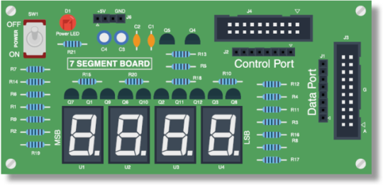
Seven Segment Display board:
Introduction:
7 segment displays are used for displaying numbers; they are useful when there is a need for counting like applications in the projects.
7 Segment board contains 4 displays and it can be interfaced to any port using the FRC cable provided with the kit. It needs two ports for operating the board, one for selection and another for segment control.
Operation:
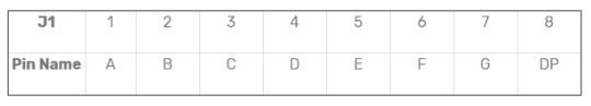
Seven segment display board contains 7 segments and a decimal point. Each data port represents a segment in the display. The segments are controlled through the firmware. The pins are configured in active low. The first pin represents A, second pin represents B and so on.
Display codes:
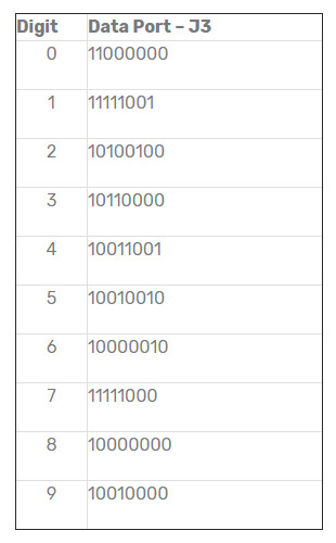
Data Port :
J3 pins are active low. That means, grounding the bit will enable the segment LED and giving a High signal will disable the segment.
Control Port:
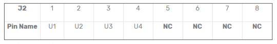
J2 pins are active high. Giving High on the bit will enable the seven segment.
NC – No Connection
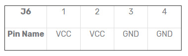
Power header:
There is a power header available on this board, J6. This can be used to test the display.
#Motor Relay Board#Keypad#Breadboard#Graphical LCD#LCD Display#I/O Board#embedded system#seven segment display board
6 notes
·
View notes
Link
LCD Controllers - Infographics!
Character liquid crystal display, construction and working, applications, advantages and disadvantages of LCD
0 notes
Photo

Basics of SPI:
SPI stands for serial peripheral interface which is an interface bus that transmits data between microcontrollers and small peripherals including sensors, SD cards and shift registers. SPI was introduced by Motorola in the year 1979 and it is also referred to as four wire serial bus. There are similar protocols available such as Microwire developed by National Semiconductor. In a simpler sense, an SPI is a four-wire single ended serial communications interface found in many microprocessors/microcontrollers, peripheral chips which enables the controllers and peripheral devices to communicate with each other. Communication with two processors is also possible with an SPI though it was developed for the purpose of communication between a host processor and it’s peripherals. SPI can operate with single master and multi master protocols even though multi-master mode is rarely used.
Synchronous Transmission:
According to the nature of the signals used to synchronise the master and slave devices, data transmission protocols are classified into two. Sychronous data transmission and asynchronous data transmission. SPI is a synchronous data transmission protocol. In synchronous data transmission, the sender and receiver share a clock with one another. Otherwise, the sender provides a timing signal which prompts the receiver to read the next bit of the data. During data transmission, if there is no data available to transmit at a given instant, a fill character will be sent to make sure that the data is always transmitted.
While in the case of asynchronous transmission, data should be transmitted without a clock signal being sent by the sender. In general case, the sender and receiver come in agreement with the speed of transmission. To make sure the data accessing follows that agreement, both the sender and the receiver set up their own internal circuits. In order to synchronise the sending and receiving units, special bits are added to each word.
Basic Connections and Data Control Lines of SPI:
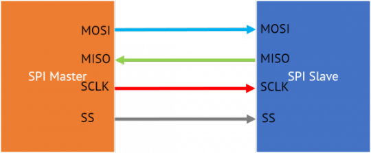
Figure shows the control lines and data lines of a single master-single slave SPI. The signal wires are MOSI, MISO, SCLK and SS. A MOSI signal is generated by the master device and it is received by the slave whereas a MISO signal is generated by a slave and received by the master. SCLK is the serial clock signal which is transmitted by the master to synchronise data transfer between the master and the slave. SS is the slave select signal which is transmitted to the chip select pin of the slave. It is an active low signal. MOSI signal is also named as serial data in (SDI) and MISO signal is named as serial data out (SDO). MOSI and MISO are data lines while SCKL and SS are control lines.
The pins are used according to the purpose. In case a device does not require an input, SDI pin may not be required and if a device does not require a output, SDO pin may not be present. Similarly if the communication is limited to one slave, then the CS pin on the particular slave device is grounded. In case of multiple slave operation, an SS signal is sent from the master to each slave device.
Working:
Most of the time, the communication will be between a single master and multiple slaves. The master generates a clock signal and using the slave select pin, it activates the slave device it wants to communicate with. The clock signal is provided to all slave devices if they are not selected for the communication at a particular time.
As discussed earlier, the master device initiates the communication. To initiate communication, the master generates clock signal which is of a frequency equal to or less than the maximum frequency the slave devices support. The slave device with which the communication has to be started is selected by pulling the chip select pin of the particular slave to low state. The slave devices which are not selected by the slave select signal will reject the clock signal as well as the MOSI signal. These slaves won’t generate the MISO signals.
The slaves have tri-state outputs which go to high impedance state when the device is not selected. Chip-select pin of these devices without this tri-state outputs will not be activated and therefor they can not share the SPI bus with other devices.
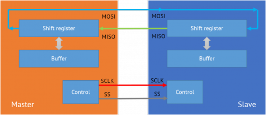
The data transmission is done in a full-duplex transmission mode. The data is sent by the master on the MOSI line and the slave reads it from the same line. Then the slave device sends a bit on the MISO line and the master reads it from the same line.
There data being transmitted are stored in shift registers associated with the master and the slave. When the master shift register shifts out a value through the MOSI line, the slave shifts the data into it’s register. While shifting data, MSB is the first one to be shifted out. After exchanging the data, the slave devices share the value and does the necessary operation. After the data transmission is done, the master stops generating the clock and the slaves are being rejected.
Clock Polarity and Phase:
Clock polarity and phase are the parameters which determine the edges of the clock. Apart from the clock frequency, the master should also configure the clock polarity and phase.
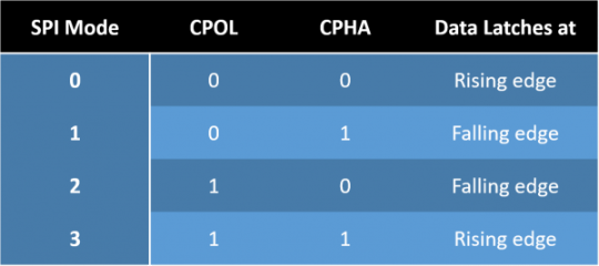
Clock polarity will determine if the clock idles high or low, if it is 1 clock idles high and if 0 clock idles low. Clock phase determines when data is transmitted relative to the clock. It’s value also depends on clock polarity, both of these parameters creates different modes in SPI.
Based on the clock polarity and clock phase, there are four modes that can be used in an SPI protocol. If the clock phase is 0, the data is latched at the rising edge of the clock with polarity 0 and at the falling edge of the clock with polarity 1. If the phase of the clock is 1, data is latched at the falling edge of the clock with polarity 0 and rising edge with polarity 1.
Master-slave Configurations:
There are different ways in which the slaves can be attached to the master. Mainly there are two types of configurations commonly used. They are daisy chain configuration and parallel configuration.
Daisy Chain Configuration:
In cascaded or daisy chain configuration, the clock lines and chip select lines of all devices are connected together. The data from the master flows through each peripheral and returns to the master. The data output of the preceding slave devicee is attached to the data in of the next device. This will give a feel of a larger slave shift register. Only a single SS line is required by the master.
Daisy Chain Configuration
Independent Slave Configuration:
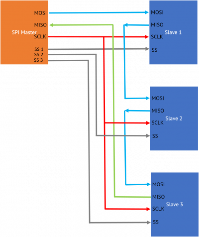
In independent slave configuration, the MISO line, MOSI lines and clock lines of all the devices are connected together. But the chip select pin of each peripheral is connected to separate slave select pins of the master.
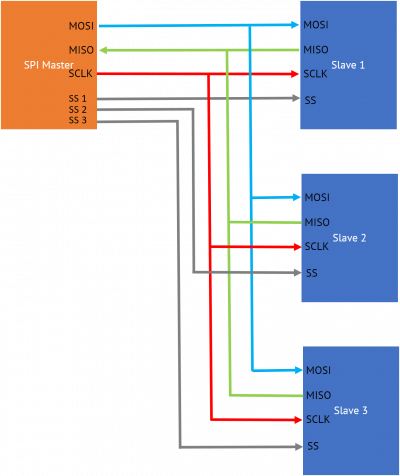
Independent slave configuration
Applications
SPI is a widely used protocol, so it is included in most of the microcontroller families. Atmel 8051 family and some AVRs use SPI for programmer communication. Some of the other chips using SPI are listed below.
Flash memories and EEPROMs, e.g: Microchip SST25VF080
SD/MMC Cards
Real Time Clock chips, e.g: Maxim DS1347
Aanalog to Digital converters, e.g: Microchip MCP3008
Battery management ICs, e.g: TI BQ76PL536
TFT LCD display drivers, e.g: ILI9341
Advantages of SPI
Supports multiple slave devices
Full duplex communication, transfer data in and out at the same time.
Significantly high data rates (in megabits/second) as compared to other serial communication stands, sometimes in megahertz range.
Simple protocol and easy to implement for single-master single-slave applications
Less complex circuitry and there is no need of external transceivers, so it is a very easy interfacing. It doesn’t care about physical interface specifications and voltage ranges.
Disadvantages
Required number of pins are high as compared to other serial protocols
Absence of in-chip addressing, it needs separate chip select of each devices
SPI doesn’t have an acknowledgement mechanism, so devices cannot confirm data reception and device existence.
SPI doesn’t have a flow control mechanism and it should be handled manually
It is a short distance communication by default, though there are solutions for extending for long-distance communication
0 notes
Photo

Have you registered yourself to our affiliate program??
1 note
·
View note
Video
youtube
EEPROM | What is EEPROM | OpenLabPro
OpenLabPro's expert engineers explains about what is an EEPROM, how they work, types of EEPROM, their advantages and disadvantages etc.Watch this video to learn more!
0 notes
Text
Learn to develop complete IoT products:
Videos covering from basics to advanced with real-life examples.
Get yourself an IoT Development board with WiFi/Bluetooth, LoRa, GSM functionalities.
Get a completion certificate that can be verified online from anywhere
Develop complete IoT applications from the scratch. Hardware, firmware, mobile apps and cloud integration.
Use WiFi, Lora and other wireless technologies to connect sensors/devices to the internet.
Learn to develop using different iot protocols like mqtt and cloud services.
Create android apps and learn to control devices using mobile phones.
Now get 25% off on your course fee! Place your order right away at OpenLabPro’s online courses for IoT
0 notes
Link
Stepper motor and its basci working principle Part 1
0 notes
Photo
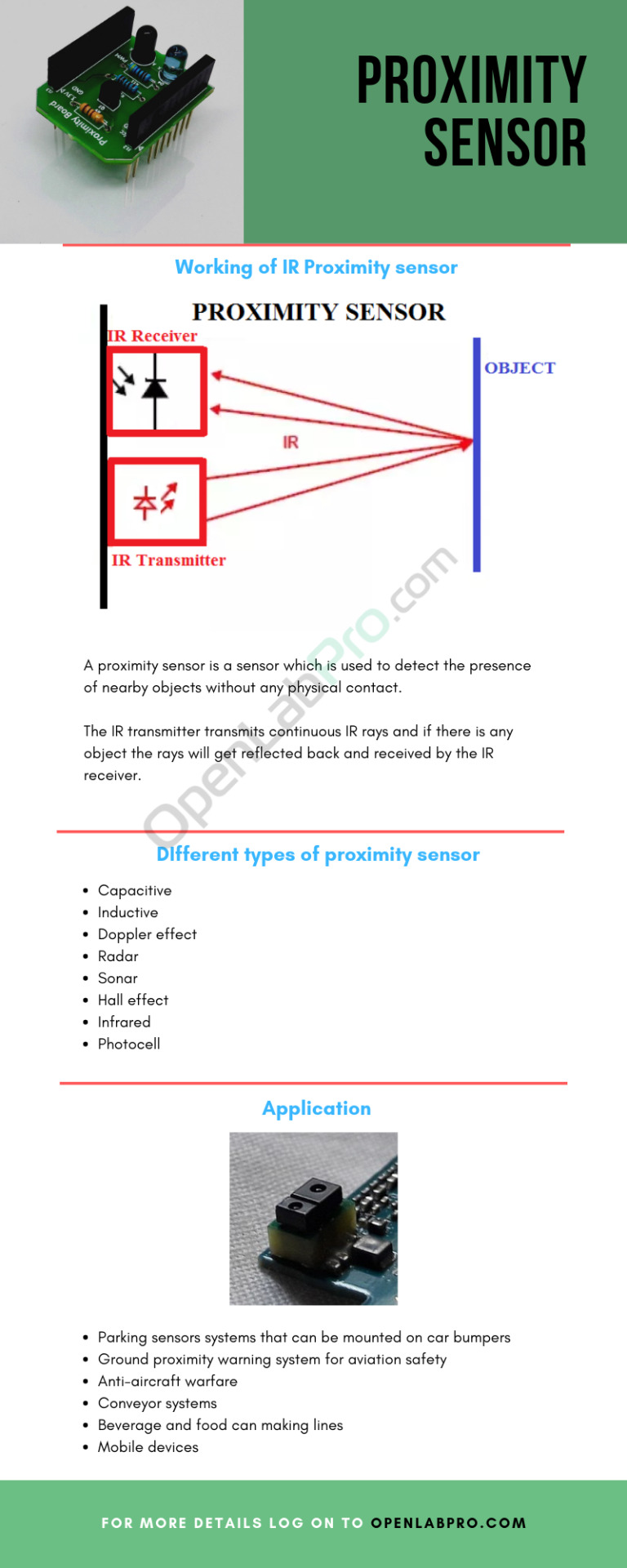
An Infograph on Proximity Sensors!
0 notes
Text
Embedded Systems Design
When we look around the world we live in, we find many man-made machines running round-the-clock. Have you ever wondered what makes them run continuously? What is the unique system inside these machines that make these devices so user-friendly and reliable? Sometimes we refer these devices as embedded systems? What is that embedded in these devices? In this chapter, we try to address such common doubts that arise in anyone who is newly subjected to these systems and terms.
Embedded systems:
In this section, we discuss what an embedded system is all about.Embedded systems are self-contained control systems or computer systems designed for particular purpose with bare necessary peripherals needed to run it. In the contemporary world, billions of embedded system devices including telephones, automobiles, electronic appliances and other digital devices are working around us, round the clock. It contains processor, memory, peripherals, and sensors etc.
While general purpose systems are meant for multiple purposes, embedded systems are designed for specific ones. Embedded systems may not have generic interfaces in most of the cases. Even if they have, it will have a specific purpose such as displaying output, giving input etc. Since they are used for a single purpose, the cost of implementing it will be less. Most of the time, embedded systems are time-critical applications which are not possible in general purpose systems.
To learn more on embedded system design visit OpenLabPro’s tutorial guide!
0 notes
Text
Interfacing Microcontrollers with SD Card
The secure digital card (SD) is a low cost, non-volatile memory card format developed by the SD Card Association. Since its inception back at the start of the century, the demand for this medium-sized, energy and space efficient, memory storage device has been growing at a fast rate. Therefore, to meet the market requirements, the SDA was set up as a non-profit organization to promote and create SD card standards. There are various topics related to the SD card such as the different device families, speed classes, smart cards, card security and so on and it is used in various markets like digital cameras, personal computers, and embedded systems. Some of the standard variations include SD, SDHC, SDXC, SD-ultra high speed etc. The microSD is the miniaturized SD memory card format with a small form factor and is widely used in various electronic devices.
What we are going to learn is the use of SD cards in an embedded system. To be specific, we will be dealing with the use of SD cards in small embedded systems.
0 notes
Note
How do I Get/Purchase Group Licence for online courses?
Group licences for online courses can be purchased through the normal route. If you want 30 licences, just add 30 quantity of the required course. We’ll convert it to a group licence when confirming the order. You can purchase online courses from Here – Online Courses or get freely by purchasing OpenLab Products.
0 notes
Video
How to Interface a hex keypad? Watch and learn!
0 notes
Photo
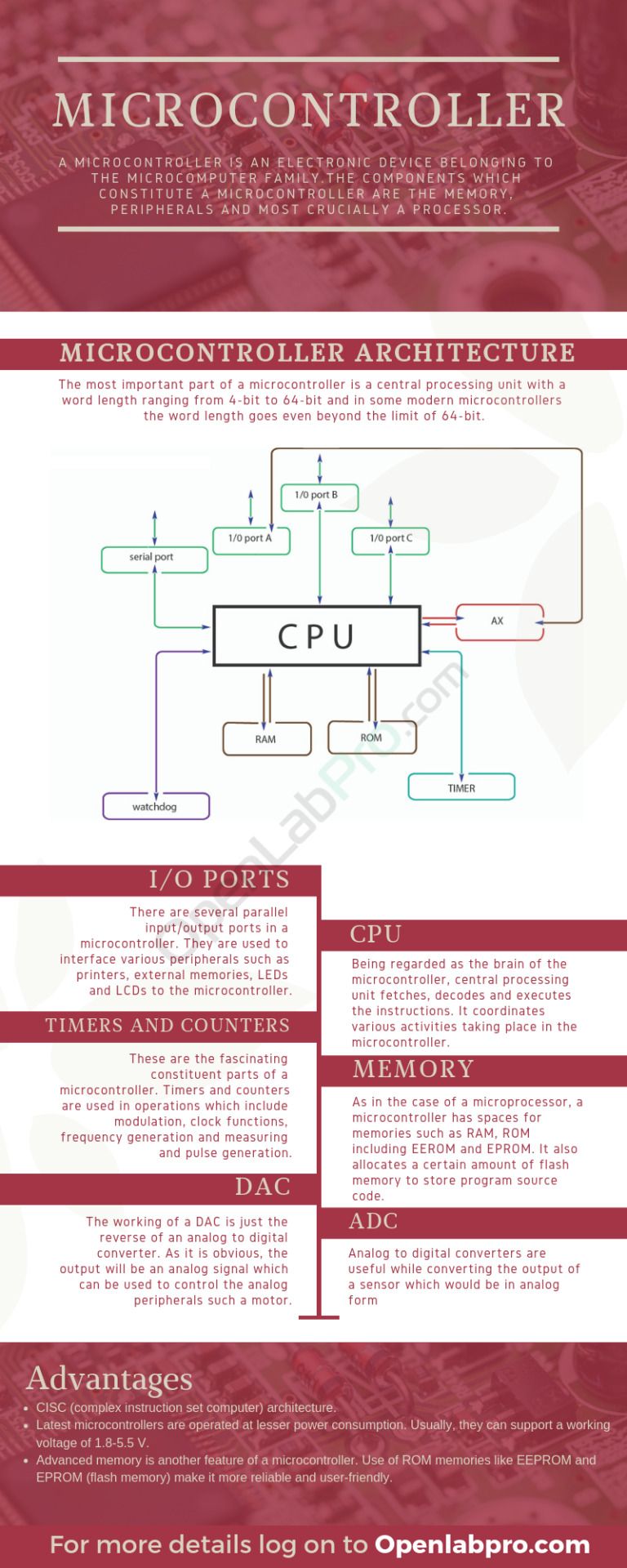
An infograph that teaches you the basics about microcontrollers, their architecture, and various features! Check it out today!
1 note
·
View note